• Acta Optica Sinica
  • Vol. 38, Issue 10, 1022002 (2018)
Zhongyu Wang**, Lianxin Zhang*, Pengfei Sun, Jian Li, and Chengzhen Yin
Author Affiliations
  • Institute of Machinery Manufacturing Technology, China Academy of Engineering Physics,Mianyang, Sichuan 621900, China
  • show less
    DOI: 10.3788/AOS201838.1022002 Cite this Article Set citation alerts
    Zhongyu Wang, Lianxin Zhang, Pengfei Sun, Jian Li, Chengzhen Yin. Mathematical Modeling Method for Generation of Gaussian-Type Removal Function in Fluid Jet Polishing[J]. Acta Optica Sinica, 2018, 38(10): 1022002 Copy Citation Text show less
    Schematic of removal function generation by rotating sweep in fluid jet polishing
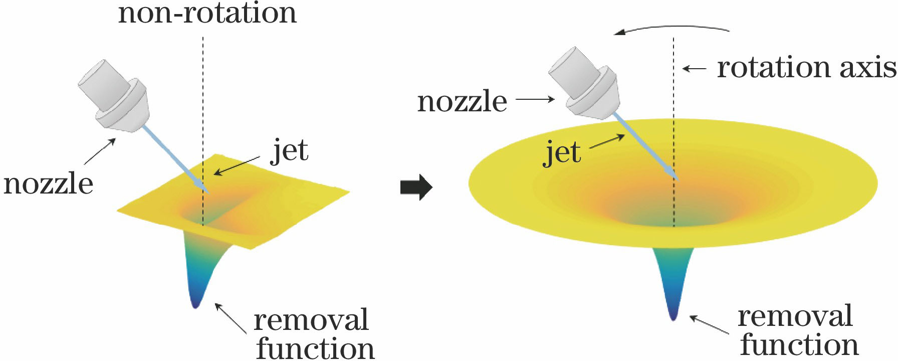
    Fig. 1. Schematic of removal function generation by rotating sweep in fluid jet polishing
    Schematic of mathematical model
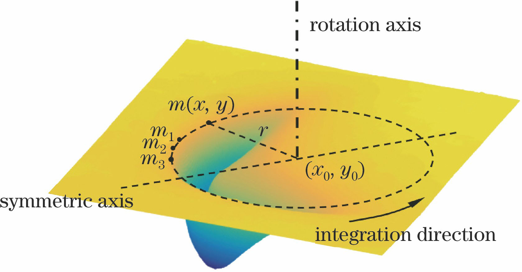
    Fig. 2. Schematic of mathematical model
    Influence of nozzle height on rotation axis when intersection points of jet beam and rotating spindle are at different positions. (a) Beneath workpiece surface; (b) on workpiece surface; (c) above workpiece surface; (d) well above workpiece surface
    Fig. 3. Influence of nozzle height on rotation axis when intersection points of jet beam and rotating spindle are at different positions. (a) Beneath workpiece surface; (b) on workpiece surface; (c) above workpiece surface; (d) well above workpiece surface
    Test platform of removal function model
    Fig. 4. Test platform of removal function model
    Distribution of rotation axis selected in verification experiment on symmetric axis of removal function. (a) 3D profile of removal function; (b) corresponding cross section
    Fig. 5. Distribution of rotation axis selected in verification experiment on symmetric axis of removal function. (a) 3D profile of removal function; (b) corresponding cross section
    Profile comparison of removal functions obtained by model calculation and practical experiment. (a) Rotation axis I; (b) rotation axis II; (c) rotation axis III; (d) rotation axis IV
    Fig. 6. Profile comparison of removal functions obtained by model calculation and practical experiment. (a) Rotation axis I; (b) rotation axis II; (c) rotation axis III; (d) rotation axis IV
    Distribution of rotation axis selected in calculation on symmetric axis of removal function. (a) 3D profile of removal function; (b) corresponding cross section
    Fig. 7. Distribution of rotation axis selected in calculation on symmetric axis of removal function. (a) 3D profile of removal function; (b) corresponding cross section
    Cross-sectional profiles of removal functions by rotating sweep obtained after calculations when rotation axes are at different positions. (a) O1; (b) O2; (c) O3; (d) O4; (e) O5; (f) O6; (g) O7; (h) O8
    Fig. 8. Cross-sectional profiles of removal functions by rotating sweep obtained after calculations when rotation axes are at different positions. (a) O1; (b) O2; (c) O3; (d) O4; (e) O5; (f) O6; (g) O7; (h) O8
    Maximum removal depth of removal function. (a) Schematic; (b) under different rotation axes
    Fig. 9. Maximum removal depth of removal function. (a) Schematic; (b) under different rotation axes
    Removal diameter of removal function. (a) Schematic; (b) under different rotation axes
    Fig. 10. Removal diameter of removal function. (a) Schematic; (b) under different rotation axes
    Surfaces processed by different methods. (a) Traditional method; (b) Gaussian-type removal function
    Fig. 11. Surfaces processed by different methods. (a) Traditional method; (b) Gaussian-type removal function
    PSD analysis of processed surfaces under different removal functions
    Fig. 12. PSD analysis of processed surfaces under different removal functions
    Parameter typeContent
    Base fluidH2O
    AbrasiveCeO2
    Mass fraction of abrasive /%1
    Output pressure /MPa0.6
    Impact angle /(°)45
    Diameter of nozzle /mm1
    Dwelling time /s240
    Nozzle height /mm7
    Rotate speed of nozzle /(r·min-1)50
    Size of workpiece /(mm×mm×mm)20×20×10
    Table 1. Parameters for verification experiment of removal function model
    Parameter typeContent
    Base fluidH2O
    AbrasiveCeO2
    Mass fraction of abrasive /%2
    Output pressure /MPa0.8
    Impact angle /(°)45
    Diameter of nozzle /mm1
    Dwelling time /s120
    Nozzle height /mm7
    Size of workpiece /(mm×mm×mm)20×20×10
    Table 2. Parameters for fabrication with fixed oblique incidence
    Zhongyu Wang, Lianxin Zhang, Pengfei Sun, Jian Li, Chengzhen Yin. Mathematical Modeling Method for Generation of Gaussian-Type Removal Function in Fluid Jet Polishing[J]. Acta Optica Sinica, 2018, 38(10): 1022002
    Download Citation