On-chip manipulation of the spatiotemporal characteristics of optical signals is important in the transmission and processing of information. However, the simultaneous modulation of on-chip optical pulses, both spatially at the nano-scale and temporally over ultra-fast intervals, is challenging. Here, we propose a spatiotemporal Fourier transform method for on-chip control of the propagation of femtosecond optical pulses and verify this method employing surface plasmon polariton (SPP) pulses on metal surface. An analytical model is built for the method and proved by numerical simulations. By varying space- and frequency-dependent parameters, we demonstrate that the traditional SPP focal spot may be bent into a ring shape, and that the direction of propagation of a curved SPP-Airy beam may be reversed at certain moments to create an S-shaped path. Compared with conventional spatial modulation of SPPs, this method offers potentially a variety of extraordinary effects in SPP modulation especially associated with the temporal domain, thereby providing a new platform for on-chip spatiotemporal manipulation of optical pulses with applications including ultrafast on-chip photonic information processing, ultrafast pulse/beam shaping, and optical computing.On-chip manipulation of the spatiotemporal characteristics of optical signals is important in the transmission and processing of information. However, the simultaneous modulation of on-chip optical pulses, both spatially at the nano-scale and temporally over ultra-fast intervals, is challenging. Here, we propose a spatiotemporal Fourier transform method for on-chip control of the propagation of femtosecond optical pulses and verify this method employing surface plasmon polariton (SPP) pulses on metal surface. An analytical model is built for the method and proved by numerical simulations. By varying space- and frequency-dependent parameters, we demonstrate that the traditional SPP focal spot may be bent into a ring shape, and that the direction of propagation of a curved SPP-Airy beam may be reversed at certain moments to create an S-shaped path. Compared with conventional spatial modulation of SPPs, this method offers potentially a variety of extraordinary effects in SPP modulation especially associated with the temporal domain, thereby providing a new platform for on-chip spatiotemporal manipulation of optical pulses with applications including ultrafast on-chip photonic information processing, ultrafast pulse/beam shaping, and optical computing.
Introduction
In integrated on-chip optical systems, manipulating an optical signal’s spatial and temporal characteristics is important when transmitting and processing information. Such manipulations have been widely applied in the fields of photonic circuits1,
2, photonic information processing3,
4, quantum information processing5, neuromorphic computing and artificial intelligence3,
5 and ultrafast optical wavefront measurement6. From theory, the control of optical signals at nanometre and ultrafast scales not only provides fundamental insights into the interaction dynamics between light and matter, but also offers an effective means for optical detection and imaging with super-spatiotemporal resolution as well as an effective platform for high-efficiency on-chip ultrafast signal processing, transmission, precision measurement, and spectroscopy. However, while the spatiotemporal manipulation of on-chip optical signals remains challenging, most current reports on this matter are constrained in either the time- or space-domain.
Recently, metasurfaces have been used to manipulate the spatiotemporal characteristics of light pulses using frequency-domain modulation methods7,
8, thereby controlling their propagation paths. Although these methods were proposed for light pulses in free space, they hint at possibilities for controlling the spatiotemporal behaviour of optical signals in on-chip systems.
Here, we propose a method based on the spatiotemporal Fourier transform (FT) to manipulate the propagation path of a femtosecond optical pulse for on-chip devices, so that during propagation the pulse exhibits different spatial properties at different instances. As a well-known mathematical tool, the FT method has been applied to an extremely wide range of applications related to optics, including spectroscopic measurements of white light9, pulse shaping10, optical computing4, and holography11, laser processing12,
13. Given that the frequency-domain FT is used to reshape the pulse in the time-domain, and similarly the spatial FT is used to reshape the spatial distribution of the light, synchronous spatiotemporal modulations of the on-chip optical pulse can be realized once the two operations are suitably combined.
To demonstrate this spatiotemporal FT method for on-chip devices, we chose surface plasmon polaritons (SPP) excited on a metal surface as carriers of on-chip optical signals, and studied the modulation effects of femtosecond SPP pulses. With their capability of breaking through the optical diffraction limit14, SPPs are widely employed in nanophotonic devices used in a variety of applications including optical storage15, optical sensing16, optical tweezers17, and Raman scattering18. In addition to nanoscale spatial resolutions, SPP pulses generated by a femtosecond laser beam enable femtosecond-scale temporal resolutions, thereby providing a research platform to investigate the manipulation of light fields and the interaction of light and matter at extremely small spatiotemporal scales. In exploring ultrafast phenomena, researchers are able to characterize the dynamics of physical and chemical events in molecular structures19 and stimulated Raman scattering (SRS) of molecules20. Here, based on research from both a theoretical model and numerical simulations, we found that with spatiotemporal FT modulations of femtosecond SPP pulses, the traditional focal spot of the SPP pulses can be transformed into a ring shape and the path of propagation of an SPP-Airy pulse can be changed at any instant, to be described below.
Results and discussion
The metallic nano-structure that performs the spatiotemporal FT modulation of SPP pulses [
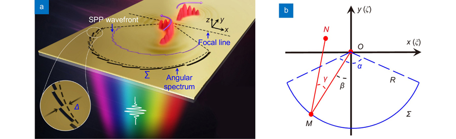
Fig. 1(a)] is composed of a gold film etched with multiple discrete nano-slits around a circular reference arc (black dashed curve) on a glass substrate. When light is incident from underneath, SPP pulses are excited and scattered from the nano-slits towards the centre of the reference arc to create a SPP focal point. Its wavefront is modulated by the angled displacement of each slit ∆ from the reference arc. In general, the spatial distribution of all the slits is designed to create a specific SPP wavefront and subsequently the desired focal field. For example, an Airy phase modulation along the lateral dimension of the beam21,
22 generates a spatially curved SPP-Airy beam near the focus. Although such displacements of the nano-slits generate various structured focal fields, these fields are nonetheless constant and not dynamically controlled. To achieve dynamic control of the SPP field, we considered applying frequency (dispersive) modulations using a femtosecond pulse of incident light with dispersive attributes, employing the frequency-domain FT method to control the temporal focusing wavefront and corresponding propagation paths of the excited SPP pulses. With frequency modulated SPPs, the wavefront of the excited SPP-Airy pulse is dynamically changed during focusing, resulting in an approximate S-shaped space-time propagation path [see
Fig. 1(a)].
Figure 1.Schematics of the excitation and spatiotemporal FT modulation of SPP pulses. (a) Nano-slits in the angular spectrum represented by a reference arc are predesigned in the gold film (200 nm in thickness) on a glass substrate (n =1.515). When illuminated with an angularly dispersed femtosecond pulse, the spatially focused SPP excited by scattering from the slits is temporally modulated through dispersion, while its converging wavefront is spatially modulated by the slits through a displacement ∆ with respect to the reference arc (black dashed curve), thereby realizing both spatial and temporal FT modulation in a SPP focusing structure. (b) In-plane SPP focusing on metal surface. The field at any point N(x,y) near the focus O(0,0) can be calculated by summing the contributions from all points, e.g., M(ξ, ζ) on a convergent SPP wavefront. γ denotes the angle of inclination of the distance with respect to the normal of the arc ∑; β denotes the angle between MO and the y-axis.
To explain the basic principle of our spatiotemporal FT method on SPP, we build a simple theoretical model. Consider an SPP pulse excited focused by a simple arc-shaped nano-slit23, its dominant electric-field component Ez perpendicular to the metal surface satisfies the two-dimensional (2-D) Helmholtz equation,
where kspp(ω) =2π/λspp(ω) denotes the wave vector of SPP, with λspp(ω) the wavelength of the SPP14, and ω the frequency of the incident light. Regardless of the time-dependent term, when the focal length R of the reference arc is much larger than the SPP wavelength λspp(ω), then, using the 2-D Helmholtz-Kirchhoff integral theorem24,
25, the time-averaged spatial distribution of the SPP in the focal region is approximately4,
26
where d =[(ξ–x)2+(ζ–y)2]1/2 denotes the distance between point M(ξ, ζ) and reference point N(x, y), U(β) the complex amplitude on arc Σ of the reference circle of radius R, with β the angle between MO (the normal of the arc) and the y axis, and γ the angle of inclination between MO and MN [
Fig. 1(b)].
After the SPP focusing structure is illuminated by the incident pulse of light, the electric field is
where α denotes the arc measure, U′(β, ω, t) =χU(β)A(ω, t), χ the SPP excitation efficiency of the slit etched on gold film, and A(ω, t) the amplitude of the incident light pulse.
Near the focus, γ ≈0 for the field distribution. Hence, we simplify
Eq. (3) to
which is expressible as a 2-D integral,
where П(·) and δ(·) are the rectangular and Dirac-Delta functions, respectively. Using approximation,
we obtain
where
and
Ignoring the constant term,
Eq. (7) forms a FT relationship between the spatiotemporal complex amplitude U″(ξ′, ζ′, ω,t) along the arc and the SPP field distribution near its geometric focus,
where F2 denotes the 2-D spatial FT. Consider a SPP pulse with arbitrary frequency ω, its spatiotemporal evolution may be obtained by integrating over all frequency components,
where F–1 denotes the 1-D temporal FT. From
Eq. (9), there is a spatial FT and a 1-D temporal FT relationship between EZ″(x, y,t) and U″(ξ′, ζ′, ω,t), namely, the spatiotemporal FT.
To verify that the spatiotemporal FT equation may be used to control the space-time properties of the SPP pulses, we consider a femtosecond incident plane wave pulse expressed as
where ω0 denotes the centre frequency of the incident pulse, t the pulse transmission time, T0 the instant when the envelope of the pulse reaches its peak amplitude, and τ the full-width at half-maximum of the power temporal duration of the pulse. With the temporal property of the SPP pulse controlled through the frequency-domain modulation, we load a frequency-dependent angular dispersion directly onto the pulsed source, its expression being
where θ denotes the incident angle (in xz plane) of the centre frequency (ω0) component. This angular dispersion loads different tilting phases onto the different frequency components of the pulse. These angularly dispersed light sources are realized experimentally using a pulsed light beam obliquely incident on a prism or a grating27,
28. To maintain the focus of the excited SPP pulse at the geometric centre of the arc, the centre frequency (ω0) component of the incident pulse must be normally incident. Therefore, for different frequency components of the angularly dispersed light pulse, the final incident angles are
Depending on the angular dispersion, different frequency components of the femtosecond pulse reach a point on the arc slit with a time delay given by
where c denotes the speed of light in a vacuum. With this time delay and
Eq. (10), the angularly dispersed femtosecond light has amplitude
Based on the above theory, we investigated the dependence of the spatiotemporal FT effects on the angular dispersion of the light beam, that is, the influence of the frequency-/time-domain modulations on the excited SPP pulses. When an arc-shaped slit is illuminated by y-polarized continuous-wave (CW) light [
Fig. 2(a)], continuous SPP pulses creating a convergent wavefront is excited forming a focal point at the geometric centre of an arc in both the time-averaged SPP field and its temporal wavefront [
Fig. 2(b)]. However, when the incident light is changed to an angularly dispersed femtosecond pulse, the focal spot of the SPP pulses is bent into a ring shape at a certain time [
Fig. 2(c)]. To reveal the principle of this extraordinary phenomenon, we calculate the time-averaged SPP focal field and the corresponding temporal wavefront from the above equations. We considered a femtosecond light beam without angular dispersion, i.e.,θ =0° in
Eq. (12) [see
Fig. 2(d–f)]. Spatially, the different frequency components of the excited SPP pulses (given in blue/green/red) are all focused and superimpose at the centre [
Fig. 2(d)], analogous to the 0th order of the FT processing of white light9. In consequence, the spatiotemporal wavefront (black dashed line) of the SPP pulses retains its focal shape during its evolution [
Fig. 2(e)]. Therefore, in terms of time, the propagation paths of the SPP pulses remain the same during focusing showing a tendency to converge (t =–6.7 fs) and forming a bright focal spot (t =0 fs), but then diverging (t =6.7 fs) [
Fig. 2(f)] (Supplementary Movie 1). In contrast, when the incident light is angularly dispersed, a frequency-related gradient phase factor must be added [
Eq. (12)], which is then transformed into a δ(·) function by the FT, resulting in a frequency-dependent shift in position in the focal plane. In this instance, in the space domain, the SPP pulses of differing frequency components focus at different positions in the focal plane [
Fig. 2(g),θ =5°] making the wavefront of the SPP pulses gradually rotate with time [
Fig. 2(h)] 26,
29, leading to a temporal redirection in propagation [
Fig. 2(i)] (Supplementary Movie 2), as seen in previous work on the spatiotemporal control of light in free space8. Thus, the SPP pulses at the focusing moment (t =0 fs) form an inverted C-shape. Furthermore, as the dispersion of the light beam increases (θ =10°), the offset distance between the focal points for the different frequency components in the focal plane become larger [
Fig. 2(j)], ensuring the wavefront of the SPP pulses rotates through a larger angle, of up to 180° [
Fig. 2(k)], to form finally a ring shape in the focal plane [t =0 fs in
Fig. 2(l)] (Supplementary Movie 3). Comparing the spatial distributions of the wavefront of the SPP pulses at t =0 fs for different angular dispersions [
Fig. 2(f),
2(i) and
2(l)], we observed that the focal points of the SPP pulses gradually bend from a single point [
Fig. 2(f)] into a ring shape (
Fig. 2(l)], verifying that our proposed method is able to modulate flexibly the space-time focusing properties of the SPP pulses. We also investigated the dependence of the spatiotemporal FT effects on several parameters, including the radius R, arc measure α, and pulse duration τ in the case of angular dispersion (θ =10°) (see Supplementary information). It is noted that the decay of SPP pulses during their propagation on the surface of the gold film could weaken the spatiotemporal modulation effect, hence the focusing radius R is always chosen smaller than the propagation length of SPP pulses of 47.18 μm26.
Figure 2.(a) Schematic of the spatial FT for a SPP with continuous-wave (CW) incident light. (b) Spatial distribution of the time-averaged field |Ez|2 excited by an 800 nm-wavelength CW source (top) and corresponding temporal wavefront in the SPP focal region (bottom). (c) Schematic of spatiotemporal FT for a SPP pulse and the angularly dispersed femtosecond laser beam, showing the instantaneous ring-shape formed by the SPP pulses in the focal region. (d) Spatial distributions of the time-averaged field |Ez|2 excited by the 756(blue)/800(green)/850(red)-nm wavelength component of the angularly dispersed femtosecond light with θ =0° in the focal region. (e) Spatiotemporal evolution of the wavefront of the SPP pulses in the focal region corresponding to (d). The blue/green/red curves mark the equiphase surfaces of the SPP pulses excited by the 756/800/850-nm wavelength components in the focal region, respectively; the black dashed curves marks wavefront of the pulse with its direction of propagation indicated by purple arrows. (f) The timing diagram for the evolution of the SPP pulse in the focal region corresponding to (e), the time instants being –6.7 fs (before focus), 0 fs (at focus), and 6.7 fs (after focus). (g–i) and (j–l) are similar in (d–f) except with θ = 5° and θ = 10°, respectively. All time-averaged fields and timing diagrams are normalized by their respective maximum values. Other settings are R =40 μm, α =180°, τ=10 fs.
Besides this frequency-/time-domain FT modulation through engineering the dispersion of incident light pulses
Fig. 2, we can also modulate the spatial FT to obtain desired phase and amplitude distributions of the SPP pulses by designing other nanostructures. Combining both modulations then achieves a variety of spatiotemporal FT manipulation effects. To verify the universality of the proposed method, we formed an SPP-Airy beam to demonstrate the spatiotemporal FT modulation of a complex SPP field. Being a non-diffractive wave, the Airy beam has interesting novel features including curved transmission and self-recovery during propagation30. Recently, different nanostructures have been designed to generate the on-chip Airy beam of the SPP31,
32, referred to as the SPP-Airy beam. Here, based on the spatial FT theory, we generated an SPP-Airy beam on a metal surface by displacing each slit by a fixed distance ∆ from the reference arc [
Fig. 1(a)]. Substituting the Airy function into
Eq. (3), the spatiotemporal field distribution of the SPP-Airy beam is obtained,
where φ =p(β +β0)3/2 is the phase of the Airy function with p and β0 constants. Thus, the corresponding offset (θ) of each slit from the reference arc is given by
Then, using the same dispersion modulation method [
Fig. 2], the SPP-Airy pulses excited by these slits are further spatiotemporally manipulated, especially in their propagation paths.
When a y-polarized femtosecond light beam is obliquely incident at an angle θ =10° to the z-axis but without angular dispersion [
Fig. 3(a)], the convergent wavefront of the excited SPP pulses is modulated by slit displacement ∆, forming the SPP-Airy pulse in the focal region. In the space-domain, the different wavelength components of the SPP-Airy pulse at the focal region are almost superimposed with the same curved shape, in good agreement with the propagation characteristics of the Airy beam31,
32. In the time-domain, the SPP-Airy pulse keeps bending to the right with time [
Fig. 3(c)] (Supplementary Movie 4). However, when excited by pulsed light with a frequency-dependent angular dispersion expressed by
Eq. (11), the SPP-Airy beam exhibits different spatiotemporal characteristics. The distributions of different frequency components of the SPP-Airy pulse are spatially separated from each other [
Fig. 3(b)]. As a result, in terms of time, the SPP-Airy pulse first bends to the left and then gradually bends to the right during propagation [
Fig. 3(e)] (Supplementary Movie 5), forming an approximate S-shaped space-time propagation path. It should be noted that, here, the function of the separated slits is only to make the SPP propagate along the curved path of the Airy beam, while the dispersion modulation is the reason that the propagation path of the SPP-Airy pulse is changed from an arc-shape to an S-shape. To verify the results of our analytical model, we used the 3-dimensional finite-difference time-domain (3D-FDTD) method to simulate the spatiotemporal evolution of the SPP-Airy pulses (Supplementary Movie 6 and 7). The FDTD results [
Fig. 3(d) and
3(f)] are in good agreement with analytical results [
Fig. 3(c) and
3(e)], proving that the proposed analytical model is efficient in reproducing the spatiotemporal behaviour of the SPP-Airy beam. Here, the slight difference between these timing diagrams is because our theoretical model only includes the propagation and focusing of SPP, while the FDTD model includes more real effects such as the scattering effects of slit and the diffraction of its edges, which makes the results more accurate. To reduce noise, a smoother/continuous structure can be designed to reduce the scattering. It is also useful to design the SPP pattern farther away from the structure to avoid scattering effects.
Figure 3.Spatiotemporal FT modulation of the SPP-Airy pulse excited by an arc array of slits [see Fig. 1(a)]. (a) The time-averaged field |Ez|2 of a pulse with centre wavelength 800 nm excited by a y-polarized femtosecond laser beam incident at angle θ =10° to the z-axis but without angular dispersion (left), and an enlargement of field |Ez|2 in the focal region (white dashed square) for the 756/800/850-nm wavelength components of the SPP pulses (right). (b) Same as (a) except with an angular dispersion modulation. The timing diagram for the evolving SPP-Airy pulse in the focal region subject to non-dispersion ((c) and (d)) and dispersion ((e) and (f)); ((c) and (e)) present analytical results and ((d) and (f)) present 3D-FDTD simulation results. The green arrow indicates the direction of propagation path of the SPP pulses at the elapsed time given in the top right corner. Other parameters are: R =30 μm, β0 =π/2, p =14, α =180°, τ=10 fs.
The above results verify that with a prescribed slit orientation, our spatiotemporal FT modulation method not only manipulates the spatial distribution of the excited SPP field but also controls the SPP pulse’s temporal wavefront and propagation paths at different moments by changing the dispersion of the incident light, thereby providing more degrees of freedom for on-chip modulation of SPP pulses. Indeed, more extraordinary effects in spatiotemporal manipulations can be generated by the combination of designing other spatial nanostructures and shaping the frequency spectrum of the incident light pulse, such as time-varying self-splitting and self-focusing effects of SPP pulses (see Supplementary information), which is superior than the modulation only in spatial domain4 or frequency domain26. Thus, with these novel spatiotemporal FT modulation effects, SPP pulses can be flexibly manipulated to bypass obstacles along an S-shaped trajectory and maintain information transmission, or perform a wide angular scanning in the ultra-fast time domain as shown in
Fig. 2, which could have great potential in many applications including photonic circuits, ultrafast on-chip photonic information processing, ultrafast pulse/beam shaping, ultrafast photo-switching and modulation, optical information encryption and optical computing. In addition, this method opens up a new way of creating novel multifunctionality in on-chip nanophotonic devices.
Conclusion
In summary, a novel spatiotemporal FT modulation method employing femtosecond pulses illuminating on-chip devices was proposed, studied, and then verified using SPP pulses in an optical setup. The angular dispersion of a femtosecond light pulse is exploited to control the excited SPP pulses in the time domain. By changing the dispersion of the light source, the wavefront of the SPP pulses in the focal plane was changed from a traditional focal point to an inverted arc-shape and even a ring shape. Combining both the frequency-domain modulation with dispersion and the spatial modulation with the nanostructure, we demonstrated that the method can generate a SPP-Airy beam with an S shape, proving the universality of the method in creating complex optical fields. Although here we study the method in theoretical model and FDTD simulation, experimental investigation for the spatiotemporal modulation of femtosecond SPP pulses can be performed using photoemission electron microscopy (PEEM) systems33-
35. We noted that this method is in theory suitable not only for SPP fields, but also for other on-chip propagating waves such as Bloch surface waves36. This work offers a new way for manipulating spatiotemporal properties of ultrafast optical pulses produced in on-chip devices with many potential applications including ultrafast photonic information processing33, ultrafast pulse shaping7,
37, beam steering8, ultrafast photo-switching and modulation38, optical computing4, and super spatiotemporal resolution imaging39.
References
[24] Clemmow PC. The Plane Wave Spectrum Representation of Electromagnetic Fields. (Oxford: Oxford University Press, 1997).
[25] Born M, Wolf E. Principles of Optics. (Cambridge: Cambridge University Press, 1999).