Abstract
Suitable optoelectronic integration platforms enable the realization of numerous application systems at the chip scale and are highly anticipated in the rapidly growing market. We report a GaN-on-silicon-based photonic integration platform and demonstrate a photonic integrated chip comprising a light source, modulator, photodiode (PD), waveguide, and Y-branch splitter based on this platform. The light source, modulator, and PD adopt the same multiple quantum wells (MQWs) diode structure without encountering incompatibility problems faced in other photonic integration approaches. The waveguide-structure MQW electro-absorption modulator has obvious indirect light modulation capability, and its absorption coefficient changes with the applied bias voltage. The results successfully validate the data transmission and processing using near-ultraviolet light with peak emission wavelength of 386 nm. The proposed complete active–passive approach that has simple fabrication and low cost provides new prospects for next-generation photonic integration.Video Introduction to the Article
1 Introduction
Photonic integration enables the realization of numerous applications at the chip scale and provides advantages of reduced size, cost, and power.1–3 Photonic integrated chips are used in various applications, including telecommunication data communication, atomic clocks, quantum communication, information processing, high-resolution spectroscopy, positioning, and navigation.4–10 InP-based photonics integration11–13 and monolithic silicon photonics14–16 are the two major integration technologies in photonics, and they each have their own unique strengths and weaknesses. InP-based photonics integration is recognized as a reliable and complete active–passive platform, but its yield and substrate size are severely limited. Furthermore, the excellent passive performance, temperature-insensitive modulator, and CMOS-compatible fabrication make monolithic silicon photonics suitable for large-scale optic-electronic integration. However, the lack of light source severely limits the development of silicon photonics.17
The emerging GaN-on-silicon platform has the potential to realize photonic integration owing to the excellent photoelectric and electrical performance of GaN-based materials.18–25 Similar to the InP-based approach, photonics integration based on a GaN-on-silicon platform can provide complete active–passive optical devices. Due to the availability of large-sized silicon wafers and good substrate thermal conductivity, low cost and high power density can be expected. Furthermore, high-performance electronic devices26–30 can be fabricated on a GaN-on-silicon platform to monolithically integrate with the photonic integrated circuit (PIC) to yield an optoelectronic integrated chip. Moreover, PICs based on a GaN-on-silicon platform can extend the light wavelength from ultraviolet to the near-infrared to meet the requirement of visible light applications, which is impossible using InP-based photonics integration and monolithic silicon photonics.31–33
Despite the presence of an inevitable Stokes shift, the emission and absorption spectra of the GaN-based multiple quantum wells (MQWs) action region overlap.34,35 Using this overlap, the light source and photodiode (PD) can be realized using the same MQW diode structure on the GaN-on-silicon platform. Combining the GaN passive components with the MQW diodes on a single chip, numerous PICs based on the GaN-on-silicon platform with various functions have been reported,36–39 which are simple, compact, and flexible compared to other III–V integration schemes. Furthermore, an interesting phenomenon is observed: the GaN-based MQW structure functions as an electro-absorption modulator40,41 with low power dissipation, compact structure, and relative low driving voltage.42–45 Therefore, herein we propose a PIC chip including a light source, modulator, PD, waveguide, and Y-branch splitter based on the GaN-on-silicon platform, wherein all the active components adopt the same MQW diode structure. The adoption of multifunction MQW completely overcomes the compatibility problem of different optical active devices and considerably reduces fabrication complexity. The proposed multichannel on-chip system has indirect light modulation capability, which is verified from various perspectives. Section 2 describes the detailed structure and fabrication of the PIC chip. The measurement results are presented in Sec. 3.
2 Structure and Fabrication
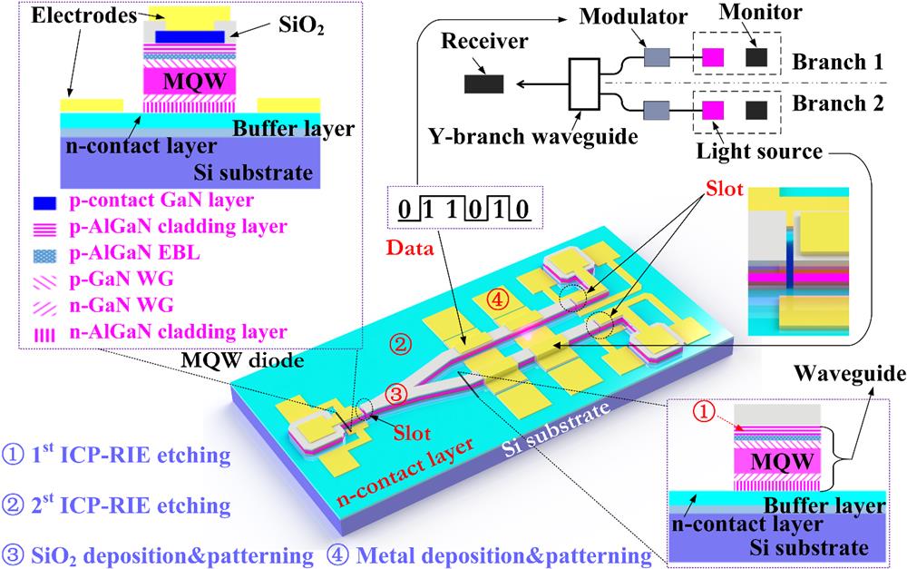
Figure 1 displays the schematic diagram of the proposed photonic integrated chip. Using two monitors, two light sources, two modulators, a receiver, a Y-branch splitter, and waveguides that are monolithically integrated on a single chip, a compact signal processing and data transmission system is constructed based on the GaN-on-silicon platform. The modulators and light sources are in the waveguide configuration, and all the active devices are based on the near-ultraviolet InGaN/AlGaN MQW diodes in which the p-contact electrodes are connected to the p-GaN contact layers. As silicon absorbs the light, the adopted waveguide configuration prevents the negative influence of the silicon substrate on the light transmission. Since the near-ultraviolet InGaN/AlGaN MQW structure has multiple functions (light emission, light modulation, and light detection) and can realize almost all the optical–electrical and electro-optical conversions required for typical signal processing and data transmission system, the proposed approach of photonic integration has the advantages of simple fabrication, low cost, and high reliability. The inset in the top left corner of Fig. 1 displays the cross-sectional diagram of the MQW structure. An isolation layer is covered on the top of the p-contact GaN layer and etched with openings for metal contact. The MQW layers are inserted in the middle of the two waveguide layers, which limits the light transmission and processing in the on-chip waveguide and improves the device performance. The Y-branch splitter has two extended branches, and each directly connects a modulator and a light source in a consistent waveguide structure to maximize the amount of light coupled in the waveguide. The waveguide structure is schematically depicted in the bottom right corner of Fig. 1 and comprises high refractive index layers sandwiched in between two AlGaN cladding layers. Due to the separated p-contact GaN layers, the modulator and light source have electrically isolated anodes and common cathodes. An MQW diode is placed near each light source to monitor the output power of the light source. The monitors can also be used to stabilize the light source intensity using a feedback control loop. The light source and monitor are isolated by a narrow slot on the waveguide with a distance of . An MQW PD as receiver is placed near the combined port of the Y-branch splitter to receive the transmitted light signal and is also isolated with the splitter using a narrow slot.

Figure 1.Schematic diagram of the proposed photonic integrated chip.
The proposed PIC chip can realize the simple functions of data transmission and signal processing. It includes various common active components that are used in photonic circuits and can be easily expanded to more sophisticated large-scale systems. Under constant current injection, the light source emits light and provides a carrier for the photonic integrated system. Moreover, the nearby MQW diode acts as a real-time monitor. Data are loaded onto the carrier through the MQW electro-absorption modulator, thereby converting the electrical signal into an optical signal. The optical signal is transmitted by the passive waveguide devices; then it reaches the receiver and is converted into an electrical signal. As a result, data transmission using light is completely realized based on the integrated chip. Furthermore, by applying two modulation signals on the modulators on the two branches, the Y-branch splitter or combiner can perform simple processing or computation of the two optical signals. The composite signals can be extracted from the receiver output.
The proposed PIC chip is designed based on the GaN-on-silicon platform using III-nitride epitaxial layers grown by metal organic chemical vapor deposition on a <111> silicon substrate with 5.08 cm in diameter. To manage the lattice mismatch between silicon and epilayers, an AlGaN buffer layer is grown first, followed by a GaN layer. Then a high-quality GaN-based MQW PN structure is deposited, wherein the MQW layer with a thickness of 52 nm is sandwiched by GaN waveguide layers and cladding layers. The detailed epilayer structures are shown in the inset in the top left corner of Fig. 1. Both InGaN/AlGaN MQW diodes and the optical waveguide can be easily implemented on this GaN-on-silicon wafer. The fabrication of the PIC prototype is only realized via four photolithography processes. First, the p-GaN contact region is defined using inductively coupled plasma reactive ion etching (ICP-RIE) with a mixture of . Next, a deep ICP-RIE is performed to pattern the MQW diode and waveguide devices with partial n-contact layer exposed. Then a 100-nm-thick thin film that is used for isolation is deposited via plasma enhanced chemical vapor deposition and patterned via wet etching. Finally, the PIC chip fabrication is completed after the formation of Ni/Au metal electrodes and separated from the 5.08 cm diameter wafer by saw dicing for the convenience of measurement. The detailed fabrication flow can refer to Fig. S1 in the Supplementary Material.
Figure 2(a) displays the scanning electron microscopy (SEM) photograph of the fabricated PIC chip. For the convenience of description, the MQW modulator and light source on the upper branch are denoted as M1 and L1, respectively. Similarly, the MQW modulator and light source on the low branch are denoted as M2 and L2, respectively. As shown in Fig. 2(b), the distance of the slot is and sufficient light can be coupled through the slots for detection. The distance of the slot can be reduced to submicrometer level by focused ion beam etching. Figure 2(c) exhibits the cross-sectional SEM image of the modulator with a waveguide width of . In the enlarged image of the waveguide edge shown in Fig. 2(d), two inclined sidewalls of the epilayers can be clearly seen, which correspond to the two ICP-RIE processes and are beneficial for the coverage of film and metal. The metal and epilayers are separated by the film at the edge region and are in direct contact in the central region of the waveguide. Figures 2(e) and 2(f) indicate the obvious stratification of the epilayers and demonstrate that the MQW is sandwiched by the GaN waveguide layers. The MQW includes four well layers in bright colors and five barrier layers in dark colors. Furthermore, a strip in dark color is clearly present on the top of the upper waveguide layer, corresponding to the p-doped AlGaN EBL that is used to block the electron overflow into the p-side.
Figure 2.Images of the fabricated photonic integrated chip. (a) SEM image of the complete chip; (b) enlarged SEM image of the slot between the receiver and Y-branch waveguide; (c) SEM cross-sectional image of the modulator; (d) enlarged SEM image of the modulator edge; (e) enlarged SEM image of the top epilayers; and (f) cross-sectional scanning transmission electron microscope image of the top epilayers.
3 Measurement and Results
To validate the effectiveness of the electrical isolation of different MQW diodes, the leakage currents between the p-contact electrodes are measured, as shown in Fig. 3(a). The modulator is ideally isolated with the receiver and monitor by the narrow slots considering that the leakage current is . Since M1 and L1 are just separated by a disconnected p-GaN contact layer on the upper branch of the waveguide, the isolation resistance is about 3.78 MΩ, but it is sufficient as the tiny leakage current on the level has almost no influence on the state of the light source when the applied working current is larger than several mA. Figure S2(a) in the Supplementary Material displays the results of remaining leakage currents between the p-contact electrodes. Figure 3(b) displays the and characteristics of the active devices in the PIC chip. The results show that the active devices have typical diode characteristics and have similar turn-on voltage near 4 V. The difference in the curves stems from the device size and fabrication errors. For example, the curve of L1 almost coincides with that of M1 because they have the same shape. The results of other MQW diodes can refer to Fig. S2(b) in the Supplementary Material. These fabrication errors are within the typical variations of our GaN-on-silicon platform process. The capacitance of the receiver increases when the voltage is first applied and then decreases to a negative value. The decrease is caused by the radiative recombination of injected carriers in the quantum well. The curves of the light source and modulator are similar and are shown in Fig. S2(c) in the Supplementary Material. Figure 3(c) exhibits the photoluminescence (PL) spectra of the MQW diode. This figure shows that the PL intensity curves have two peak values. The long peak wavelength is , which corresponds to the absorption of the InGaN/AlGaN MQW. The short peak wavelength, near 366 nm, stems from the absorption of GaN. For the electroluminescence (EL) spectrum shown in Fig. 3(d), the peak wavelength is about 386 nm, which has a small blueshift compared to the PL spectrum due to the change of the energy band caused by the current injection. The 28-nm overlap between the photocurrent absorption spectrum (RS) and EL spectra indicates that the MQW diode can act as a PD for detecting the optical power emitted from the light-emitting diode of the same MQW structure. The tests are performed in a dark environment to avoid the influence of external light. However, it is also found that the normal environmental light does not have much influence on the measurement results. The reason may be due to the waveguide structure that limits the light transmission. If much higher precision is required in the practical applications, a package with a light shield can be adopted. The EL intensity under different injection currents and RS under different applied bias voltages are provided in Figs. S2(d) and S2(e) in the Supplementary Material, respectively. Based on the RS results, the response intensity increases with the reverse bias voltage, but the wavelength shift is not obvious. Therefore, in contrast to the Ge/SiGe MQW with strong quantum-confined Stark effect, the InGaN/AlGaN MQW diode used as the modulator is mainly based on the change of absorption amplitude. Figure 3(e) exhibits the detected photocurrent of the receiver and monitor1 versus the injection currents on L1. The ratio of the two currents is and quite stable. From the photocurrent ratio, the waveguide transmission loss is determined to be . Figure 3(f) and Fig. S2(f) in the Supplementary Material display the currents of the receiver and monitor1 versus the voltage under different applied currents on L1. Under dark condition at room temperature, the leakage currents of both PDs are extremely low (). When L1 is turned on by applying current, the photocurrents of the receiver and monitor1 obviously change and increase with the applied current. Moreover, due to shorter distance between L1 and monitor1 than that between L1 and the receiver, the photocurrent of monitor1 is larger than that of the receiver under the same bias conditions. When L2 is turned on, the receiver and monitor2 present similar photocurrent responses, as shown in Figs. S2(g)–S2(i) in the Supplementary Material, respectively. The results indicate the effectiveness of the MQW diode for light-power detection.
Figure 3.(a) Leakage currents between the p-contact electrodes; (b) characteristics of MQW diodes and characteristics of the receiver; (c) PL spectra of the MQW diode; (d) RS and EL spectra of the MQW diode; (e) detected photocurrent of the receiver and monitor1 versus the injection currents on L1; (f) detected photocurrent of the receiver under different applied currents on L1.
Figure 4(a) displays the detected photocurrent of the receiver versus the bias voltage on M1 under different injection currents on L1. Clearly, the absolute value of the receiver photocurrent decreases with increasing reverse bias voltage on M1. The detected photocurrent of the receiver reflects the light power after modulation. The results indicate that a larger reverse bias voltage on M1 results in more light absorption of the modulator due to the absorption coefficient change. Subsequently, less light will reach to the receiver and induce a smaller photocurrent. Therefore, the photocurrent change of the receiver reflects distinctive modulation effect. Assuming that the photocurrent has a linear relation with the received light power, the extinction ratio of the modulator with the bias voltage from 0 to is calculated to be 30%, according to the curve under 30 mA current on L1, as shown in Fig. S3(b) in the Supplementary Material. Since the sensitivity of the receiver is small, larger injection currents on the L1 lead to larger detected current changes and benefits for signal processing. In contrast, the detected current of monitor1 does not change with the bias voltage on M1, signifying that the light source works steadily without the interference of the modulation signal. The test with M2 and L2 on the lower branch affords similar modulation characteristics, as shown in Figs. S3(a) and S3(c) in the Supplementary Material. The deviation between the results of the two branches stems from the fabrication errors but does not influence the system function. To validate the effectiveness of modulation, a square signal with a frequency of 20 Hz and of 4 V ( to ) is applied on M1, and the detected currents of receiver and monitor1 are measured, as shown in Fig. 4(b). The results show that the receiver receives the square signal and the monitor current remains constant. Hence, the test system demonstrates no significant cross talk, and the isolation between the light source and modulator on the same waveguide through the p-contact layer separation is sufficient for system performance. When a 20 mA current is injected on L2 and a square signal of 1 Hz frequency is applied on M2, a flickering spot can be seen clearly on the low branch (see Video 1). Figure 4(c) displays the photocurrent waveform of the receiver under different injection currents when a square signal (20 Hz) is applied on M1. The received waveform is coincident with the input square wave, and the response amplitude increases with the injection current on L1. Moreover, two modulation signals with different frequencies (20 and 200 Hz) are simultaneously applied on the modulators. Figure 4(d) exhibits the waveform of the receiver. The injection currents on the two light sources are different for discriminating signals from different channels. Thus we can infer that the two signals with different frequencies can be simultaneously transmitted using light through the PIC chip. The received waveforms of the receiver under other frequencies are presented in Figs. S3(d)–S3(g) in the Supplementary Material. The reproducibility and stability of the PIC chip are evaluated via cyclic tests at a modulation frequency of 1 Hz on M1. As shown in Fig. 4(e), the detected photocurrent of the receiver is highly stable over 2000 cycles, and the photocurrent waveforms in different periods are consistent.
Figure 4.(a) Detected photocurrent versus the bias voltage on M1; (b) detected photocurrent of receiver and monitor1 when a square signal is applied on M1; (c) photocurrent waveform of the receiver under different injection currents on L1; (d) received waveform of the receiver when two modulation signals with different frequencies (20 and 200 Hz) are simultaneously applied on the modulators. Inset displays the PIC chip in the working state (Video 1, MPEG, 9.1 MB [URL: https://doi.org/10.1117/1.APN.2.4.046003.s1). (e) Detected photocurrent of the receiver at a modulation frequency of 1 Hz on M1 over 2000 circles. The injected current on L1 is 20 mA, and the modulation voltage ranges from to .
Utilizing the two branches structure, the PIC chip can perform simple processing or computation of two signals using light. Figure 5(a) presents the combined signal detected by the receiver with an incident signal of varying duty cycles applied on M1. The duty cycle of another signal applied on M2 is fixed at 50% and the frequency of both signals (from to ) is fixed at 100 Hz. The injection currents of L1 and L2 are 20 and 16.8 mA, respectively, and the bias voltage on the receiver is . Figure 5(b) shows the combined signal detected by the receiver with the two incident signals in different phases. The results denote that the superposition of two signals is successfully realized using light without interference to the electric circuit. Moreover, the relation of the two incident signals can be inferred through the combined signal detected by the receiver. Using the proposed integration scheme, more sophisticated and powerful PIC chips could potentially be built for optical computing and data transmission. By injecting a 20 mA constant current on L1, the pseudo-random binary sequence (PRBS) data stream ( of 4 V with a of ) is indirectly loaded onto the light carrier through M1 and reverted to an electrical signal through the receiver. The receiver signal is then sent to the oscilloscope for characterization. The maximum data transmission rate through indirect modulation using MQW electro-absorption modulator is ; its eye diagram is shown in Fig. 5(c). Because M1 and receiver are under reversed bias with extremely low power consumption, the total power consumption is mainly determined by the light source (about 142 mW). To analyze the limiting factor for the indirect modulation, the PRBS data transmission using direct on–off keying modulation through the light source is tested, and the rate can reach 40 Mbps, as shown in Fig. 5(d). The data transmission rate through indirect modulation is likely limited by the modulation amplitude but not by the bandwidth of the receiver. Furthermore, using direct and indirect modulations at a single light path, two types of data can be transmitted simultaneously, or one of the modulations can encrypt data transmission of another modulation signal.
Figure 5.Combined signals detected by the receiver with (a) an incident signals with varying duty cycles on M1; (b) the incident two signals in different phases. Eye diagram using (c) indirect modulation at a data transmission rate of 10 kbps and (d) direct modulation at a data transmission rate of 40 Mbps.
4 Conclusion
In this study, we proposed a complete active–passive photonic integration scheme based on the GaN-on-silicon platform and realized a PIC comprising a light source, modulator, PD, waveguide, and Y-branch splitter. All the active devices are based on the same near-ultraviolet InGaN/AlGaN MQW structure, which is a distinguishing feature from other photonic integration approaches and considerably reduces the fabrication complexity and cost. The effectiveness of the integrated components and system performance were validated via the measurement. Additionally, the data transmission and processing using light were successfully demonstrated. With the improvement of III-nitride etching accuracy in the future, the proposed integration scheme provides a potential competitive solution for next-generation photonic integration, especially for the sensing field, for which the requirement of integration density is not very high.
Jiabin Yan received his BS degree in microelectronics from Shanghai University, Shanghai, China, and his PhD in microelectronics and solid-state electronics from the Southeast University, Nanjing, China, in 2013 and 2018, respectively. He is currently a lecturer at Peter Grünberg Research Centre, Nanjing University of Posts and Telecommunications, Nanjing, China. The discipline of his research focuses on the GaN-based optoelectronic devices, optoelectronic integrated circuit (OEIC), thermoelectric/photoelectric energy harvesters, and RF MEMS devices.
Li Fang received his BS degree in electronic information engineering from Qingdao University of Technology, Shandong, China, in 2022. He is currently pursuing his MS degree in electronic information at Nanjing University of Posts and Telecommunications. His current research interests include the GaN-based optoelectronic devices, OEIC, thermoelectric/photoelectric energy harvesters, and RF MEMS devices.
Zhihang Sun received his BS degree in communication engineering from Nanjing Tech University, Jiangsu, China, in 2022. He is currently pursuing his MS degree in electronic information at Nanjing University of Posts and Telecommunications. His current research interests include monolithic integrated GaN LEDs, vertical-structure LEDs, and visible light communications.
Hao Zhang received his BS degree in automation from Nanjing Institute of Technology, Nanjing, China, and his MS degree in electronics and communication engineering from Nanjing University of Posts and Telecommunications, Nanjing, China, in 2016 and 2019, respectively. He is currently pursuing his PhD in signal and information processing at Nanjing University of Posts and Telecommunications. Currently, he is working on photoelectronic integration system based on GaN chips.
Jialei Yuan received his MS degree from Nanjing University of Posts and Telecommunications in 2018. He is currently pursuing his PhD at Nanjing University of Posts and Telecommunications. He has published four papers in Applied Physics Express, Semiconductor Science Technology, Optics Communications, and Japanese Journal of Applied Physics, respectively. His current research is on-chip integration of optoelectronic devices on GaN-on-silicon platform.
Yan Jiang received her MS degree in information and communication engineering from Nanjing University of Posts and Telecommunications, China. She is currently an assistant experimentalist at the College of Telecommunications and Information Engineering Nanjing University of Posts and Telecommunications. Her current research interests include the light-emitting diodes and its application in visible light communication.
Yongjin Wang received his PhD from Shanghai Institute of Microsystem and Information Technology, Chinese Academy of Sciences, Shanghai, China, in 2005. He has received numerous scholarships including the Humboldt Foundation Scholarship, the JSPS Special Researcher Scholarship, and the Royal Society for Engineering Scholarship. Since 2011, he has been a professor at Nanjing University of Posts and Telecommunications. His current research is to conduct III-nitride monolithic photonic circuit for visible light communication.
References
[1] C. Cole, B. Huebner, J. E. Johnson. Photonic integration for high-volume, low-cost applications. IEEE Commun. Mag., 47, S16-S22(2009).
[2] A. Liu et al. Silicon photonic integration for high-speed applications. Proc. SPIE, 6898, 117-126(2008).
[3] R. Soref. The past, present, and future of silicon photonics. IEEE J. Sel. Top. Quantum Electron., 12, 1678-1687(2006).
[4] Y. Yang et al. Multi-dimensional spatial light communication made with on-chip InGaN photonic integration. Opt. Mater., 64, 160-165(2017).
[5] C. R. Doerr. Silicon photonic integration in telecommunications. Front. Phys., 3, 37(2015).
[6] M. A. G. Porcel et al. Silicon nitride photonic integration for visible light applications. Opt. Laser Technol., 112, 299-306(2019).
[7] Z. L. Newman et al. Architecture for the photonic integration of an optical atomic clock. Optica., 6, 680-685(2019).
[8] A. Argyris et al. Photonic integrated device for chaos applications in communications. Phys. Rev. Lett., 100, 194101(2008).
[9] M. F. Soares et al. High-performance InP PIC technology development based on a generic photonic integration foundry, M3F–3(2018).
[10] D. F. Welch et al. Large-scale InP photonic integrated circuits: enabling efficient scaling of optical transport networks. IEEE J. Sel. Top. Quantum Electron., 13, 22-31(2007).
[11] M. Smit et al. An introduction to InP-based generic integration technology. Semicond. Sci. Technol., 29, 083001(2014).
[12] M. Smit, K. Williams, J. V. D. Tol. Past, present, and future of InP-based photonic integration. APL Photonics, 4, 050901(2019).
[13] J. E. Bowers, A. Y. Liu. A comparison of four approaches to photonic integration, 1-3(2017).
[14] P. Koonath, T. Indukuri, B. Jalali. Monolithic 3-D silicon photonics. J. Lightwave Technol., 24, 1796(2006).
[15] X. Chen, C. Li, H. K. Tsang. Device engineering for silicon photonics. NPG Asia Mater., 3, 34-40(2011).
[16] J. C. Rosenberg et al. Monolithic silicon photonic WDM transceivers, 1-3(2017).
[17] Z. Wang et al. Novel light source integration approaches for silicon photonics. Laser Photonics Rev., 11, 1700063(2017).
[18] T. Boles. GaN-on-silicon—present capabilities and future directions, 020001(2018).
[19] T. Boles. GaN-on-silicon present challenges and future opportunities, 21-24(2017).
[20] A. Y. Liu, J. Bowers. Photonic integration with epitaxial III–V on silicon. IEEE J. Sel. Top. Quantum Electron., 24, 1-12(2018).
[21] W. Cai et al. Monolithic photonic integrated circuit with a GaN-based bent waveguide. J. Micromech. Microeng., 28, 065003(2018).
[22] M. Mikulics et al. Nano-LED driven phase change evolution of layered chalcogenides for Raman spectroscopy investigations. FlatChem, 36, 100447(2022).
[23] H. X. Jiang, J. Y. Lin. Nitride micro-LEDs and beyond: a decade progress review. Opt. Express, 21, A475-A484(2013).
[24] M. Mikulics, J. Mayer, H. H. Hardtdegen. Cutting-edge nano-LED technology. J. Appl. Phys., 131, 110903(2022).
[25] Q. Wang et al. Monolithic semi-polar (1ī01) InGaN/GaN near white light-emitting diodes on micro-striped Si (100) substrate. Chin. Phys. B, 28, 087802(2019).
[26] J. Yan, J. Piao, Y. Wang. An enhancement mode MOSFET based on GaN-on-silicon platform for monolithic OEIC. IEEE Electron Device Lett., 41, 76-79(2019).
[27] K. S. Boutros et al. Normally-off 5A/1100 V GaN-on-silicon device for high voltage applications, 1-3(2009).
[28] N. Herbecq et al. Above 2000 V breakdown voltage at 600 K GaN-on-silicon high electron mobility transistors. Phys. Status Solidi-a, 213, 873-877(2016).
[29] S. Yoshida et al. A 76 GHz GaN-on-silicon power amplifier for automotive radar systems, 665-668(2009).
[30] A. Pantellini et al. GaN-on-silicon evaluation for high-power MMIC applications, 223-227(2012).
[31] D. F. Feezell et al. Development of nonpolar and semipolar InGaN/GaN visible light-emitting diodes. MRS Bull., 34, 318-323(2009).
[32] S. Zhou et al. High power GaN-based LEDs with low optical loss electrode structure. Opt. Laser Technol., 54, 321-325(2013).
[33] X. Dai et al. Flexible light-emitting diodes based on vertical nitride nanowires. Nano Lett., 15, 6958-6964(2015).
[34] R. W. Martin et al. Exciton localization and the Stokes’ shift in InGaN epilayers. Appl. Phys Lett., 74, 263-265(1999).
[35] R. Zheng, T. Taguchi. Stokes shift in InGaN epitaxial layers. Appl. Phys. Lett., 77, 3024-3026(2000).
[36] Y. Wang et al. Full-duplex light communication with a monolithic multicomponent system. Light Sci. Appl., 7, 1-7(2018).
[37] X. An et al. Ultrafast miniaturized GaN-based optoelectronic proximity sensor. Photonics Res., 10, 1964-1970(2022).
[38] J. Yuan et al. GaN directional couplers for on-chip optical interconnect. Semicond. Sci. Technol., 32, 045001(2017).
[39] M. Feng et al. On-chip integration of GaN-based laser, modulator, and photodetector grown on Si. IEEE J. Sel. Top. Quantum Electron., 24, 1-5(2018).
[40] M. Xie et al. Uniting a III‐nitride transmitter, waveguide, modulator, and receiver on a single chip. Adv. Eng. Mater., 23, 2100582(2021).
[41] C. Shen et al. High-modulation-efficiency, integrated waveguide modulator–laser diode at 448 nm. ACS Photonics, 3, 262-268(2016).
[42] G. T. Reed et al. Silicon optical modulators. Nat. Photonics, 4, 518-526(2010).
[43] J. E. Roth et al. Optical modulator on silicon employing germanium quantum wells. Opt. Express, 15, 5851-5859(2007).
[44] Y. Rong et al. Quantum-confined Stark effect in Ge/SiGe quantum wells on Si. IEEE J. Sel. Top. Quantum Electron., 16, 85-92(2009).
[45] Y. Kuo et al. Strong quantum-confined Stark effect in germanium quantum-well structures on silicon. Nature, 437, 1334-1336(2005).