• Journal of Infrared and Millimeter Waves
  • Vol. 42, Issue 5, 622 (2023)
Chun-Ke WEI1, Jin-Wei RAO2、*, and Bi-Mu YAO1、2、**
Author Affiliations
  • 1State Key Laboratory of Infrared Physics,Shanghai Institute of Technical Physics,Chinese Academy of Sciences,Shanghai 200083,China
  • 2School of Physical Science and Technology,ShanghaiTech University,Shanghai 201210,China
  • show less
    DOI: 10.11972/j.issn.1001-9014.2023.05.007 Cite this Article
    Chun-Ke WEI, Jin-Wei RAO, Bi-Mu YAO. Research progress of cavity magnon-polariton systems[J]. Journal of Infrared and Millimeter Waves, 2023, 42(5): 622 Copy Citation Text show less
    (a)Schematic of the linearly coupled magnon(m)and photon(a)system. g is the coupling strength,κm and κa are the dissipation rates of magnon and microwave cavity modes.(b)Four kinds of coupling regimes separated by the relative strength between the coupling rate and dissipation rates of photon and magnon subsystem.(c)eigenfrequency’s real partsRe(ω1,2) of the energy splitting.(d)eigenfrequency’s imaginary parts Im(ω1,2)of mode’s damping exchange.
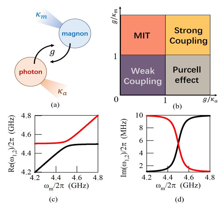
    Fig. 1. (a)Schematic of the linearly coupled magnon(m)and photon(a)system. g is the coupling strength,κm and κa are the dissipation rates of magnon and microwave cavity modes.(b)Four kinds of coupling regimes separated by the relative strength between the coupling rate and dissipation rates of photon and magnon subsystem.(c)eigenfrequency’s real partsRe(ω1,2 of the energy splitting.(d)eigenfrequency’s imaginary parts Im(ω1,2of mode’s damping exchange.
    (a)Schematic of the waveguide assembly cavity.(b-d)impact of sample thickness and cavity length on the coupling strength g.(b) d = 0.5 mm,W = 85 mm.(c) d = 1 mm,W = 85mm.(d)d = 0.5 mm,W = 242 mm.(d)functions of |S21| and(ω - ωc)/2π in three different cases[71]
    Fig. 2. (a)Schematic of the waveguide assembly cavity.(b-d)impact of sample thickness and cavity length on the coupling strength g.(b) d = 0.5 mm,W = 85 mm.(c) d = 1 mm,W = 85mm.(d)d = 0.5 mm,W = 242 mm.(d)functions of |S21| and(ω - ωc)/2π in three different cases71
    (a)The A-P-M device is consist of a passive cavity(P),an active cavity(A)with a voltage tuneable gain(Gn),and an YIG sphere with magnons(M).(b)The A-P cavity circuit’s Q-factor and Gnare respectively tunable up to 81,500 and 360,000,with the increase of V.(c)| S21 | spectra measured(circles)and fitted(curve)at ∆ = 0 and V = 7V.(d)| S21 | spectra measured at ∆ = 0 and V = 7V with various Rabi frequencies Ωf determined from the mode splitting.(e)The ratio of Rabi frequencies Ωf/Ω0 which is measured(circles)and calculated(curve)is changing with the increase of V and Gn . The maximum uncertainty caused by the error from fitting the Rabi frequency is shown by the error bar[72]
    Fig. 3. (a)The A-P-M device is consist of a passive cavity(P),an active cavity(A)with a voltage tuneable gain(Gn),and an YIG sphere with magnons(M).(b)The A-P cavity circuit’s Q-factor and Gnare respectively tunable up to 81,500 and 360,000,with the increase of V.(c)| S21 | spectra measured(circles)and fitted(curve)at = 0 and V = 7V.(d)| S21 | spectra measured at = 0 and V = 7V with various Rabi frequencies f determined from the mode splitting.(e)The ratio of Rabi frequenciesf/Ω0 which is measured(circles)and calculated(curve)is changing with the increase of V and Gn . The maximum uncertainty caused by the error from fitting the Rabi frequency is shown by the error bar72
    (a)Schematic diagram illustrates a tunable A-P-M device consisting of an active cavity(A)and a varactor-loaded passive cavity(P),where Vc is the control voltage applied to the varactor and V is fixed at 7V.(b)The dispersions of the magnon quintuplet as a function of external field H with Vc = -3 V.(c)Magnon quintuplet evolution with control voltage Vc for an external field of 120 mT(indicated by arrow in panel(b))[74]
    Fig. 4. (a)Schematic diagram illustrates a tunable A-P-M device consisting of an active cavity(A)and a varactor-loaded passive cavity(P),where Vc is the control voltage applied to the varactor and V is fixed at 7V.(b)The dispersions of the magnon quintuplet as a function of external field H with Vc = -3 V.(c)Magnon quintuplet evolution with control voltage Vc for an external field of 120 mT(indicated by arrow in panel(b))74
    (a)Radiative damping dominates energy dissipation in magnon mode when coupled with photon mode in a circular waveguide cavity,as shown in(a). Experimental setup of the coupled system is shown in(b). Simulated LDOS ρ⊥ at d=0mm and d=6.5mm are shown in(c)and(e),respectively. Measured and calculated linewidth-frequency relations are shown in(d)and(f),with black circles indicating measured intrinsic linewidths[75]
    Fig. 5. (a)Radiative damping dominates energy dissipation in magnon mode when coupled with photon mode in a circular waveguide cavity,as shown in(a). Experimental setup of the coupled system is shown in(b). Simulated LDOS ρ at d=0mm and d=6.5mm are shown in(c)and(e),respectively. Measured and calculated linewidth-frequency relations are shown in(d)and(f),with black circles indicating measured intrinsic linewidths75
    Analogue of dynamic Hall effect demonstrated in a cavity magnon polariton system with external static magnetic field along z-direction. Polariton flow and charge current exhibit similar deflection patterns in y-direction,shown in(a)and(b). Microwave transmission spectra and output voltage measurements at 0mT and 203mT are shown in(c)-(f),with solid lines indicating results from the dynamic Hall model. Experimental setup(g)includes a mechanical phase shifter,and(h)shows transmission amplitude mapping with different phase differences between input ports. Logic table for response of side modes(SMs)and central mode(CM)is shown in(i)[83]
    Fig. 6. Analogue of dynamic Hall effect demonstrated in a cavity magnon polariton system with external static magnetic field along z-direction. Polariton flow and charge current exhibit similar deflection patterns in y-direction,shown in(a)and(b). Microwave transmission spectra and output voltage measurements at 0mT and 203mT are shown in(c)-(f),with solid lines indicating results from the dynamic Hall model. Experimental setup(g)includes a mechanical phase shifter,and(h)shows transmission amplitude mapping with different phase differences between input ports. Logic table for response of side modes(SMs)and central mode(CM)is shown in(i)83
    Schematic diagrams of electromagnetic absorption limitations in symmetric two-port and perfect absorption in singleport systems are shown in(a)and(b),respectively.(c)Coherent perfect absorption(CPA)strategy is shown for a two-port system.(d)MIPA system is shown,with near-perfect absorption achieved through the interference between hybrid photonmagnon modes. Energy level schematic is shown in(e). Squared amplitudes of reflection and transmission at θ = 0◦ and 90◦ are shown in(f)and(g). Theoretical function of maximal absorption rate is shown in(h),with green and yellow indicating the parameters of currently used and modified intersecting cavities,and white dashed line indicating maximal absorption rate over 90%[85]
    Fig. 7. Schematic diagrams of electromagnetic absorption limitations in symmetric two-port and perfect absorption in singleport systems are shown in(a)and(b),respectively.(c)Coherent perfect absorption(CPA)strategy is shown for a two-port system.(d)MIPA system is shown,with near-perfect absorption achieved through the interference between hybrid photonmagnon modes. Energy level schematic is shown in(e). Squared amplitudes of reflection and transmission at θ = 0◦ and 90◦ are shown in(f)and(g). Theoretical function of maximal absorption rate is shown in(h),with green and yellow indicating the parameters of currently used and modified intersecting cavities,and white dashed line indicating maximal absorption rate over 90%85
    ddtd̂xdy̑m̂q̂=-iΩd̂xd̂ym̂q̂+κd00κqp1inΩ=ω˜d0gdsin θ00ω˜dgdcos θ0gdsin θgdcos θω˜mgq00gqω˜q7
    Table 1. [in Chinese]
    Chun-Ke WEI, Jin-Wei RAO, Bi-Mu YAO. Research progress of cavity magnon-polariton systems[J]. Journal of Infrared and Millimeter Waves, 2023, 42(5): 622
    Download Citation