
Yang Yue, Qian Bin, Liu Chang, Qiu Jianrong. Progress in 3D Laser Printing of Glass[J]. Laser & Optoelectronics Progress, 2018, 55(1): 11409
- Laser & Optoelectronics Progress
- Vol. 55, Issue 1, 11409 (2018)
![(a) Shrinkage photo of printed samples; (b) printed samples using glass powders with different particle sizes (both scales of millimeter-level)[6]](/richHtml/lop/2018/55/1/011409/img_1.jpg)
Fig. 1. (a) Shrinkage photo of printed samples; (b) printed samples using glass powders with different particle sizes (both scales of millimeter-level)[6]
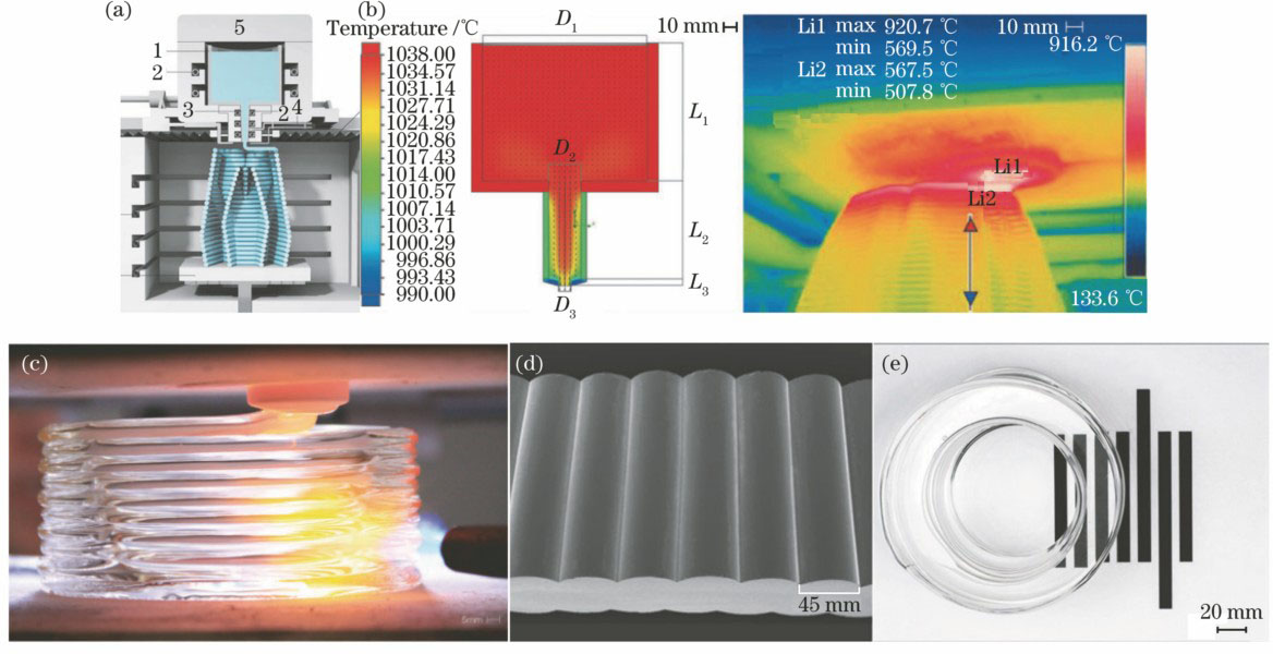
Fig. 2. (a) Structure cross section of printing system; (b) temperature distribution in the printing process; (c) nozzle printing; (d) SEM image of a sample; (e) optical transparency of printed parts (top view of a 70-mm-tall cylinder)
Fig. 3. 3D glass printing system and process control
Fig. 4. Effect of firing temperature on (a) density and (b) bend strength of SLS alumina-glass composites
Fig. 5. Change of missing part surface and break as laser power increasing
Fig. 6. Schematic of stereo lithography apparatus of glass
Fig. 7. Glass samples. (a) Glass sample under UV curing; (b) glass sample using 3D printing method (both samples have been made heat treatment)
Fig. 8. Transmittance spectrum of 3D glass sample
Fig. 9. Microstereo lithography of hollow castle gate (scale bar of 270 μm)
Fig. 10. Microstereo lithography of an exemplary microfluidic chip (inset scale bar of 200 μm)
Fig. 11. Optical device. (a) Micro-optical diffractive structure; (b) microlens fabricated using greyscale lithography (both scale bars of 100 μm)

Set citation alerts for the article
Please enter your email address
© Copyright 2018-2021 | Chinese Laser Press. All Rights Reserved 沪ICP备15018463号-20