• Laser & Optoelectronics Progress
  • Vol. 59, Issue 8, 0815005 (2022)
Han Lu1, Qinwei Ma1、*, and Shaopeng Ma2
Author Affiliations
  • 1School of Aerospace Engineering, Beijing Institute of Technology, Beijing 100081
  • 2School of Naval Architecture, Ocean & Civil Engineering, Shanghai Jiao Tong University, Shanghai 200240
  • show less
    DOI: 10.3788/LOP202259.0815005 Cite this Article Set citation alerts
    Han Lu, Qinwei Ma, Shaopeng Ma. Camera Array-Based Optical Measurement Approach and System for Occluded Targets[J]. Laser & Optoelectronics Progress, 2022, 59(8): 0815005 Copy Citation Text show less
    Imaging model and parallax of planar camera array
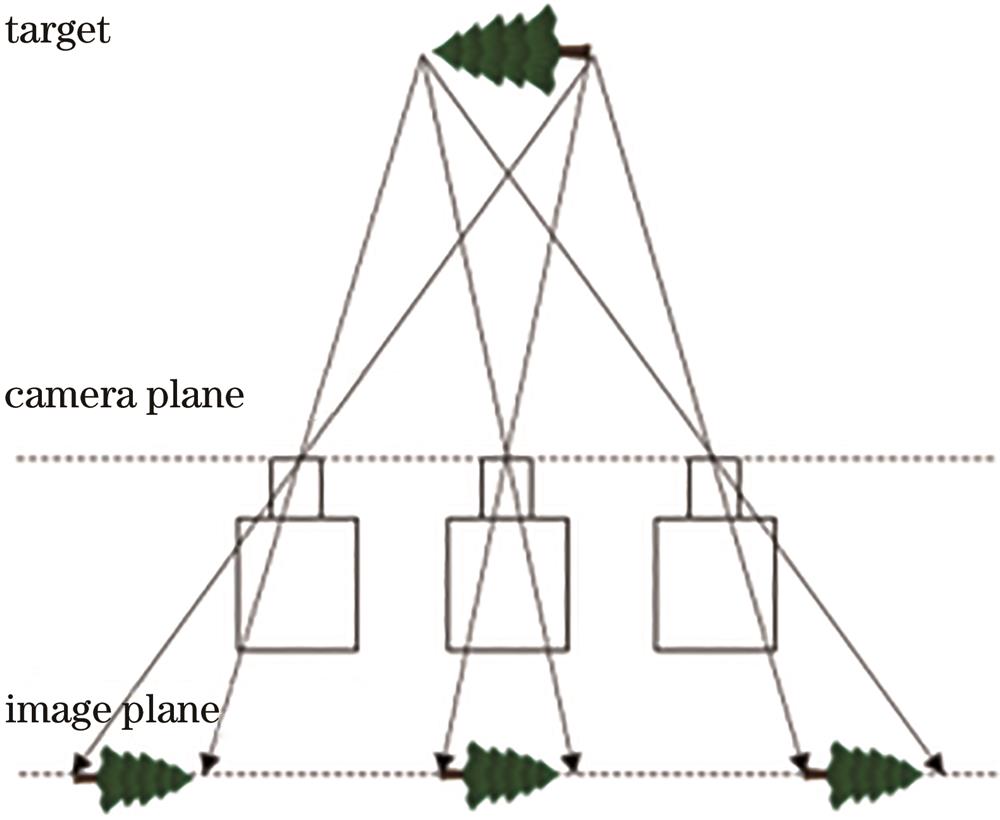
    Fig. 1. Imaging model and parallax of planar camera array
    Imaging model of a point in space
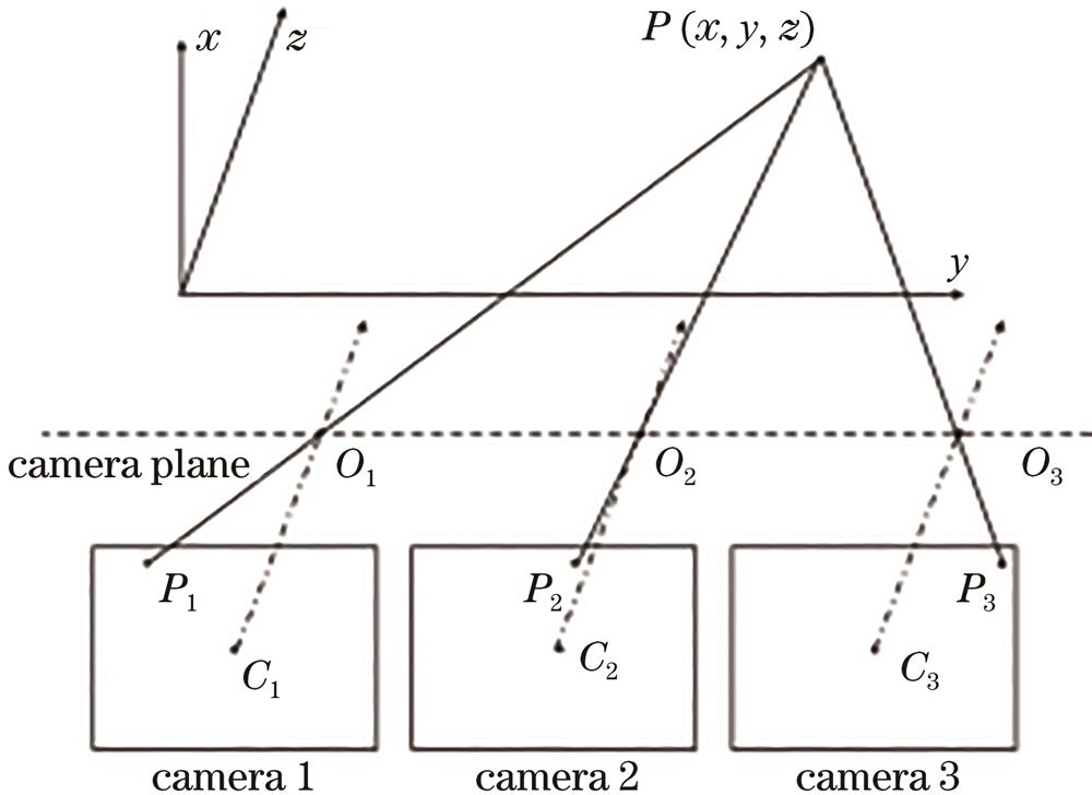
    Fig. 2. Imaging model of a point in space
    Schematic of virtual camera array
    Fig. 3. Schematic of virtual camera array
    Simulated synthetic aperture imaging process
    Fig. 4. Simulated synthetic aperture imaging process
    Gray centroid method. (a) Ideal dot gray distribution; (b) dot gray distribution of synthetic image; (c) recognition position and theoretical value
    Fig. 5. Gray centroid method. (a) Ideal dot gray distribution; (b) dot gray distribution of synthetic image; (c) recognition position and theoretical value
    Synthetic image and fitting result. (a) Composite images with different number of cameras; (b) recognition result with different number of cameras; (c) recognition error with different number of cameras
    Fig. 6. Synthetic image and fitting result. (a) Composite images with different number of cameras; (b) recognition result with different number of cameras; (c) recognition error with different number of cameras
    Corner identification method. (a) Conventional image marker points; (b) composite image marker points; (c) conventional image gray distribution; (d) composite image gray distribution
    Fig. 7. Corner identification method. (a) Conventional image marker points; (b) composite image marker points; (c) conventional image gray distribution; (d) composite image gray distribution
    Corner recognition method of synthetic image. (a) Corner gray distribution; (b) corner recognition result; (c) corner recognition number under different number of cameras
    Fig. 8. Corner recognition method of synthetic image. (a) Corner gray distribution; (b) corner recognition result; (c) corner recognition number under different number of cameras
    Schematic of inner contour and outer contour
    Fig. 9. Schematic of inner contour and outer contour
    Synthetic aperture image
    Fig. 10. Synthetic aperture image
    Contour iterative simulation. (a) Outline drawing; (b) least square fitting; (c) iterative fitting circle center; (d) area magnification; (e) relationship between iteration times and identification error
    Fig. 11. Contour iterative simulation. (a) Outline drawing; (b) least square fitting; (c) iterative fitting circle center; (d) area magnification; (e) relationship between iteration times and identification error
    Contour iteration method. (a) Grayscale distribution map; (b) identification points O1 and O2; (c) enlarged view; (d) final result O
    Fig. 12. Contour iteration method. (a) Grayscale distribution map; (b) identification points O1 and O2; (c) enlarged view; (d) final result O
    Raspberry Pi and CSI camera
    Fig. 13. Raspberry Pi and CSI camera
    Synthetic aperture measurement system. (a) Proposed measurement system; (b) USB power supply system
    Fig. 14. Synthetic aperture measurement system. (a) Proposed measurement system; (b) USB power supply system
    Experimental system and three marking points
    Fig. 15. Experimental system and three marking points
    Original images, composite images, and recognition results of three kinds of marked point. (a) Proposed method; (b) gray centroid method; (c) corner identification method
    Fig. 16. Original images, composite images, and recognition results of three kinds of marked point. (a) Proposed method; (b) gray centroid method; (c) corner identification method
    Comparison of the results obtained by proposed method and gray centroid method
    Fig. 17. Comparison of the results obtained by proposed method and gray centroid method
    Schematic of motion measurement experiment
    Fig. 18. Schematic of motion measurement experiment
    Trajectory comparison. (a) Original image and synthetic aperture image; (b) recognition result
    Fig. 19. Trajectory comparison. (a) Original image and synthetic aperture image; (b) recognition result
    Displacement curve of simple pendulum
    Fig. 20. Displacement curve of simple pendulum
    Deployable truss structure
    Fig. 21. Deployable truss structure
    Original images and composite images. (a) Experiment 1; (b) experiment 2
    Fig. 22. Original images and composite images. (a) Experiment 1; (b) experiment 2
    Recognition results. (a) Experiment 1; (b) experiment 2
    Fig. 23. Recognition results. (a) Experiment 1; (b) experiment 2
    Fitted curves. (a) Experiment 1; (b) experiment 2
    Fig. 24. Fitted curves. (a) Experiment 1; (b) experiment 2
    Han Lu, Qinwei Ma, Shaopeng Ma. Camera Array-Based Optical Measurement Approach and System for Occluded Targets[J]. Laser & Optoelectronics Progress, 2022, 59(8): 0815005
    Download Citation