• Chinese Optics Letters
  • Vol. 20, Issue 1, 011602 (2022)
Huanhuan Su1, Huizhen Zhang1, Wenjing Wu2, Xiang Wang1, Guanghou Wang1, and Lin Zhou1、*
Author Affiliations
  • 1National Laboratory of Solid State Microstructures, School of Physics, College of Engineering and Applied Sciences, Nanjing University, Nanjing 210093, China
  • 2Department of Electrical Engineering, The Pennsylvania State University, University Park, Pennsylvania 16802, USA
  • show less
    DOI: 10.3788/COL202220.011602 Cite this Article Set citation alerts
    Huanhuan Su, Huizhen Zhang, Wenjing Wu, Xiang Wang, Guanghou Wang, Lin Zhou. Chemically engineered dendrite growth of uniform monolayers MoS2 for enhanced photoluminescence [Invited][J]. Chinese Optics Letters, 2022, 20(1): 011602 Copy Citation Text show less

    Abstract

    Large area and uniform monolayer MoS2 is of great importance for optoelectronic devices but is commonly suffering from rather weak photoluminescence. Here, by engineering the concentration profiles of gaseous chemicals through extra trace amounts of water, we demonstrate the uniform dendrite-type growth of monolayer MoS2 unraveled by spatially resolved fluorescence spectroscopy, which exhibits macroscopic monolayer flakes (up to centimeter scale) with photoluminescence intensity of orders of magnitude higher than conventional chemical vapor deposition monolayer MoS2. Both spectroscopic evidence and theoretical models reveal that the fast-fractal dendrite growth can be ascribed to the extra introduced water sources that generate sufficient aqueous gas around the S-poor regions nearby the central-axis zone, leading to highly efficient Mo sources transport, accelerated S atom corrosion nearby grain edges, and/or defect sites, as well as enhanced photoemission intensity. Our results may provide new insight for high throughput fabrication of MoS2 monolayers with high yield photoluminescence efficiency.

    1. Introduction

    Atomically thin two-dimensional (2D) transition metal dichalcogenides (TMDs)-like monolayer MoS2 has evidenced tremendous advancements in the field of catalysis[13], nanoelectronics[4,5], and optoelectronics[68] thanks to the intriguing physical properties such as the abrupt phase transition from indirect to direct bandgap semiconductors once they are down to one atomic layer thickness[911]. Especially, uniform monolayer MoS2 crystals with a large area and strong photoluminescence (PL) yield are highly desired for optoelectronic devices[12,13], which drives the fast development of versatile fabrication techniques[1416]. Among various procedures, chemical vapor deposition (CVD) is widely regarded as the most practical route towards large-area uniform monolayers because of its low cost, high scalability, and operation simplicity[17,18]. A broad range of CVD prepared monolayer MoS2 can be ascribed into two primary types: (1) the homogeneous growth such as triangles, hexagons, and stars[18,19], which feature high crystal symmetry as well as spatially uniform appearance (like continuous films), beneficial for large-area uniform monolayers (up to wafer scale), and relatively low defect density except for intentionally doping[20,21]; (2) the heterogeneous growth such as dendrites or fractal branches, which are more favorable for enhanced PL due to considerable edges and/or defect sites[22]. However, most of the reported dendrite-type monolayer MoS2 samples are discontinuous (with low surface coverage of monolayers) and thus incompatible with mainstream transfer processes of 2D optoelectronic devices[2325]. Therefore, the spatially uniform dendrite-type monolayer MoS2 with large area and strong fluorescence is still challenging but urgently needed thus far. In this work, we demonstrate the continuous dendrite growth of uniform monolayer MoS2 up to centimeter (cm) scale with chemical engineering of spatially dependent concentration of the trace amounts of water sources (CuSO4·5H2O) and temperature control, which exhibits pronounced PL enhancement of orders of magnitude with respect to the conventional triangular monolayer MoS2. The large area and fast dendrite growth as well as pronounced PL enhancement can be ascribed to off-stoichiometric-ratio growth due to aqueous gas-assisted generation of appropriate density S-poor sites in a diffusion-limited growth configuration[2628], which is unraveled by microscopic fluorescence spectroscopy. Our results can provide a highly scalable fabrication strategy for ultra-bright uniform monolayer TMDs for next generation optoelectronic devices.

    2. Fabrication Process and Design

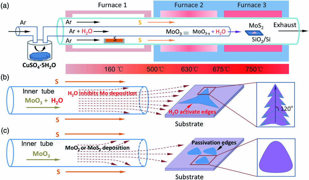
    Figure 1(a) schematically illustrates the rationally-designed three-zone CVD setup for the large area dendrite-type growth of monolayer MoS2 with spatially dependent temperature control (see Supplementary Materials, Note S1, Fig. S1 for details), showing the well-defined spatial concentration and sublimation phase transition of sulfur (S), MoO3 and growth temperature of MoS2, respectively. In the experiment, except for the conventional precursors MoO3 and S powders positioned in lower and higher temperature zone, respectively, extra water precursors (CuSO4·5H2O powders) are added in the inner tube to introduce a trace amount of water alongside the MoO3 gas flow. As shown in Fig. 1(a), we use CuSO4·5H2O to provide a trace of water due to the excellent stability at high temperature. With keeping CuSO4·5H2O at room temperature, aqueous vapor can be carried into the inner tube alongside the MoO3 gas. Under the assistance of the Ar carrier gas together with the trace amount of aqueous gas, the sublimation rate of MoO3 can be increased[29], and the spontaneous diffusive transfer and deposition of Mo sources on the side wall of the inner tube can be effectively inhibited [Figs. 1(b) and 1(c)], resulting in the sufficient MoO3 gaseous sources reaching the target SiO2/Si substrate, beneficial for large area growth of monolayer MoS2. The trace amount of water sources results in chemical corrosion of the as-grown perfect crystals, generating the defects and/or S vacancies. The introduction of considerable edges and/or defect sites into monolayer MoS2 can provide more radiation recombination centers, beneficial for the fluorescence enhancement[22]. Therefore, with the increased chemical corrosion of water, the generated higher density defects can lead to stronger fluorescence intensity. In addition, the trace amount of aqueous gas can simultaneously be carried to the substrate as well, which in turn activates the water-assisted corrosion reactions, especially nearby the edges and/or defect points, and thus in turn accelerates the crystal growth of MoS2 (Supplementary Materials, Note S2), leading to the fast dendrite growth of large-area uniform monolayer MoS2 with respect to the conventional triangular growth in a self-limiting configuration [see amplified schematic in Figs. 1(b) and 1(c), respectively].

    (a) Schematic diagram of the CVD setup for growth of MoS2. The locations of S, MoO3, and SiO2/Si substrate are exactly displayed. (b) Schematic of the growth of MoS2 with the extra H2O sources. (c) Schematic of the conventional triangular growth of MoS2 without H2O sources.

    Figure 1.(a) Schematic diagram of the CVD setup for growth of MoS2. The locations of S, MoO3, and SiO2/Si substrate are exactly displayed. (b) Schematic of the growth of MoS2 with the extra H2O sources. (c) Schematic of the conventional triangular growth of MoS2 without H2O sources.

    3. Chemically Engineered Photoluminescence

    The representative optical images of as-grown dendrite-type monolayer MoS2 with a trace amount of water sources are shown in Supplementary Materials, Fig. S3, which can be extremely fast grown up to cm scale and is much larger than conventional triangular samples. For detailed comparison, Fig. 2 further demonstrates the amplified optical photographs and microscopic fluorescence images of the dendrite and triangular monolayer MoS2, respectively. Apart from the much larger flake sizes, Fig. 2(a) shows in detail that the rough edges of the flakes clearly resemble the branch feature that distinctly deviates from the well-known smooth zigzag or armchair profile reported in literatures[30,31], indicating that heterogeneous growth driven by extra chemical reactions may happen except for homogeneous growth of MoS2. More specifically, the fluorescence image of the dendrite-type monolayer MoS2 [Fig. 2(b)] unravels two additional features compared to the conventional ones [Fig. 2(f)]. (1) The PL intensity of the dendrite monolayer is much higher than triangular MoS2 monolayers almost all over the flakes (30 times, except for the edge sites), as demonstrated in Figs. 2(d) and 2(h), respectively. (2) The extremely bright dendrite monolayers exhibit self-similar branch-like microscopic nature composed of first, second, and higher-order branches (so called the dendrite-type monolayer). More specifically, the hierarchical branching-like feature in the 2D fluorescence pattern [Fig. 2(b)] is well reproduced by the phase diagram of the atomic force microscopy (AFM) image of the same dendrite flake [Fig. 2(c)], which is commonly related to the spatially anisotropic distributions of S atoms in CVD samples[32,33]. Note that with the dark-field spectroscopy evidence for the water-assisted corrosion reactions from the merging sites of different branches (Supplementary Materials, Fig. S2), we suggest that there is a correlation between chemical compositional heterogeneity and the trace amount of water induced chemical corrosion. In addition, because the corrosion generated S-vacancies sites are of considerable density in area under the self-limiting growth condition, the PL intensity can be significantly enhanced compared to the homogeneous arrangement of monolayer MoS2 (merely bright nearby the edges), indicating the engineering capability of trace water sources to the intensity of the fluorescence spectroscopy. To further confirm the detailed structure of MoS2 samples, AFM characterizations were performed. The AFM phase images [Figs. 2(c) and 2(g)] exhibit the uniformity of the dendrite MoS2 and conventional triangular MoS2, respectively. In Fig. 2(c), the phase resolved AFM image shows patterned phase contrast with agreement of the outline of backbone and secondary branches, which matches well with the dendritic profile of fluorescence emission [Fig. 2(b)].

    (a), (e) Microscopic optical photographs, (b), (f) fluorescence spectra, (c), (g) phase diagrams of AFM images, and (d), (h) photoluminescence (PL) spectra for (a)–(c) dendrite and (e)–(g) conventional triangular monolayers MoS2, respectively. Scale bar: (a), (b) = 50 µm, (e), (f) = 10 µm, (c), (g) = 6 µm.

    Figure 2.(a), (e) Microscopic optical photographs, (b), (f) fluorescence spectra, (c), (g) phase diagrams of AFM images, and (d), (h) photoluminescence (PL) spectra for (a)–(c) dendrite and (e)–(g) conventional triangular monolayers MoS2, respectively. Scale bar: (a), (b) = 50 µm, (e), (f) = 10 µm, (c), (g) = 6 µm.

    (a) Bright-field image of a uniform MoS2 dendrite with a large size. (b) Diffraction pattern of the area marked with black circle in (a) and the vector indicate the two families, KS and KMo. (c) Amplitude of the AFM image of the prepared monolayer MoS2 by water-assisted CVD procedure. (d) A line scan profile shows the diffraction intensity of framed spots in (b). (e) Representative Raman spectrum of the monolayer MoS2 dendrites grown on Si/SiO2 substrate. (f) shows the line profile along the white line in (c). The measured thickness of the monolayer is ∼1 nm.

    Figure 3.(a) Bright-field image of a uniform MoS2 dendrite with a large size. (b) Diffraction pattern of the area marked with black circle in (a) and the vector indicate the two families, KS and KMo. (c) Amplitude of the AFM image of the prepared monolayer MoS2 by water-assisted CVD procedure. (d) A line scan profile shows the diffraction intensity of framed spots in (b). (e) Representative Raman spectrum of the monolayer MoS2 dendrites grown on Si/SiO2 substrate. (f) shows the line profile along the white line in (c). The measured thickness of the monolayer is ∼1 nm.

    In order to identify the crystalline structure of dendrite MoS2, transmission electron microscopy (TEM) as well as AFM characterization was performed. Figure 3(a) shows the bright-field TEM image of a compact dendritic MoS2 in a copper hole. The selected-area electron diffraction (SAED) patterns [Fig. 3(b)] show a six-fold symmetry hexagonal lattice, which indicates the highly crystalline structure of as-grown MoS2 sample [Fig. 3(d)]. The height profile of dendrite MoS2 is about 1 nm in Fig. 3(c), which shows that the MoS2 is monolayer [Fig. 3(f)]. In addition, the difference between the two characterized Raman vibration modes [Fig. 3(e)] was 19.7cm1, which further indicates that the MoS2 film is monolayer in nature.

    The role of trace water induced chemical corrosion, as well as the off-stoichiometric-ratio dendrite growth, can further be inferred from the position-dependent fluorescence images of monolayer MoS2 samples with the trace amount of water carefully tuned. Figure 4 shows the detailed comparison of microscopic optical photographs as well as fluorescence images of dendrite-type MoS2 samples I, II, III with the off-central-axis distance decreased gradually, respectively. It is clearly demonstrated that the nucleation sites move close to the central axis of the CVD tube, in which area the precursor gaseous atmosphere possesses increasing Mo and water concentration while decreasing S concentration (from I to III). Because of the unique core-shell tube profile as well as the carrier gas distribution, as depicted in Fig. 3(a), the water concentration is gradually increased from area I to area III, which suggests an increase of defect density and thus enhanced PL intensity from I to III. In the meantime, the monolayer flake sizes increase distinctly [see Figs. 4(b)4(d) for comparison]. These phenomena can be attributed to the gradual increase of water concentration from region I to III. In region III, where gaseous water concentration is so high (with respect to the S concentration), the water corrosion reactions in the proximity of grain boundary and/or defect sites happen sufficiently across the entire area of the monolayer flake, which provides high density of S-poor sites and thus greatly enhances the fluorescence intensity as well as accelerates the growth velocity. However, as the deposition position is far from the center area of the Mo/water precursor flow, the water concentration and water-assisted edge activation reactions decrease distinctly, giving rise to rather weak PL intensity [Fig. 4(h)].

    (a) Schematic diagram of growth of MoS2 in the representative regions of I, II, III. (b)–(d) Optical microscopy (OM) images of the monolayer MoS2 in the regions of I, II, III, respectively. The domain evolves from the isolated monolayer in I to the continuous MoS2 flakes in III. (e)–(g) are the fluorescence spectroscopy (FM) images corresponding to (b)–(d), respectively. The intensity of fluorescence increases gradually from (e) to (g). (h) PL intensity in areas I, II, and III of the monolayer MoS2, respectively. Scale bars: 100 µm.

    Figure 4.(a) Schematic diagram of growth of MoS2 in the representative regions of I, II, III. (b)–(d) Optical microscopy (OM) images of the monolayer MoS2 in the regions of I, II, III, respectively. The domain evolves from the isolated monolayer in I to the continuous MoS2 flakes in III. (e)–(g) are the fluorescence spectroscopy (FM) images corresponding to (b)–(d), respectively. The intensity of fluorescence increases gradually from (e) to (g). (h) PL intensity in areas I, II, and III of the monolayer MoS2, respectively. Scale bars: 100 µm.

    Finally, to unravel the physical mechanism of the dendrite-type growth of monolayer MoS2, a theoretical model is proposed to resemble the heterogeneous dendrite growth, as depicted in Fig. 5 (see more details in Supplementary Materials, Note S3, Figs. S6 and S7). Note that there are at least three features of the dendrite-type monolayers from the experiment [see the amplified microscopic fluorescence image in Figs. 5(a) and 5(b)]. (1) The overall flake exhibits a clear self-similar hierarchical framework of the 1st, 2nd, and 3rd branches with an inter-angle of 120°, respectively. (2) The fluorescence pattern is spatially heterogeneous with respect to the hierarchical branches: the PL emission of monolayer MoS2 in the framework area is weaker, while PL emission from the monolayer in the adjacent area between different sub-branches is much stronger, which is noted as homogeneous and heterogeneous arrangements, respectively. (3) The edges of the dendrite-type monolayer flake are so rough that they resemble leaves in nature (Supplementary Materials, Fig. S4), and the PL intensity is pronounced. In the simulation model in Fig. 5(c) (Supplementary Materials, Note S3), we suggest that there are three types of basic building blocks for the self-assembly of large area monolayers under the self-limiting growth condition [upper row in inset (i) of Fig. 5(c)], the inter-angles of which are 120° either in the clockwise or anti-clockwise direction. Note that the atomic assembly in each of the three uniform configurations should be a homogeneous arrangement [lower row in inset (i) of Fig. 5(c)]. In these areas, the PL emission should be weak since the recombination centers of perfect lattices are rather limited, which forms the framework in Fig. 5(c) or dendrite-like branches in Fig. 5(a), respectively. Now, consider the roles of the trace amount of water sources. Due to the water-assisted chemical corrosion, the S atoms located in the defect-rich area, for example, the grain edges as well as adjacent regions between different sub-branches, tend to be severely removed, leading to high density of S-poor sites or highly activated recombination centers in heterogeneous arrangement [see inset (ii) of Fig. 5(c)]. Thus, the PL emission of these areas [noted as red dashed squares in Fig. 5(c)] can be significantly enhanced. The interlaced heterogeneous (S-poor) and homogeneous (S-rich) areas finally result in the branch-like fluorescence profile in Fig. 5(a). In addition, accompanying increased S atoms being knocked out from the monolayers, S-poor areas become even more heterogeneous and thus more chemically active. Such positive feedback can further accelerate the growth velocity and generate considerably large monolayer flakes (up to cm scale, see details in Supplementary Materials, Figs. S1 and S3), which is ideal for scalable fabrication of ultra-bright large-area monolayer MoS2.

    Analysis of the CVD-grown uniform dendritic monolayer MoS2 morphology. (a) Fluorescence microscope image for uniform dendritic monolayer MoS2. The hierarchical structures are marked by arrows, i.e., yellow for primary backbone, green and blue for the secondary and tertiary branches. The axial angles between different hierarchical branches (I and II, II, and III) have the same 120° angle. (b) The close-ups of areas marked by the solid rectangles in (a). (c) Atomic structure arrangement diagram of uniform dendritic MoS2. The region in the red circle has more defects, where fluorescence is stronger.

    Figure 5.Analysis of the CVD-grown uniform dendritic monolayer MoS2 morphology. (a) Fluorescence microscope image for uniform dendritic monolayer MoS2. The hierarchical structures are marked by arrows, i.e., yellow for primary backbone, green and blue for the secondary and tertiary branches. The axial angles between different hierarchical branches (I and II, II, and III) have the same 120° angle. (b) The close-ups of areas marked by the solid rectangles in (a). (c) Atomic structure arrangement diagram of uniform dendritic MoS2. The region in the red circle has more defects, where fluorescence is stronger.

    4. Conclusion

    In conclusion, we experimentally evidenced the large area dendrite-type monolayer MoS2 with pronounced PL intensity by engineering the spatially dependent temperature/concentration, especially the extra trace amount of water sources. The overall PL intensity of the monolayers is enhanced at least an order of magnitude with respect to conventional homogeneous MoS2 flakes. The fast growth velocity (large grain sizes) as well as significant PL enhancement can be ascribed to the trace-water-assisted Mo source transport and position selective corrosion effect, which finally generates the alternative arrangement of homogeneous (S-rich) and heterogeneous (S-poor) areas in a self-similar dendrite flake. Our study can provide a clear physical picture of the heterogeneous CVD growth mechanism, beneficial for enabling meaningful strategy for scalable fabrication of optically bright monolayer MoS2.

    5. Methods

    5.1. Preparation and transfer of monolayer MoS2 flakes

    MoS2 monolayer flakes were transferred onto the TEM grid for TEM measurements using a poly(methyl methacrylate) (PMMA)-assisted method. A PMMA film was spin-coated on the surface of MoS2 grown on the used substrate at 4000 r/min for 60 s. Then, the sample was heated at 160°C for 10 min. After that, the samples were soaked in NaOH solution to separate the PMMA/MoS2 films from the substrate. Next, the PMMA/MoS2 layer was rinsed three times with deionized water. The film was immediately mounted on a TEM grid for imaging. Finally, the PMMA/MoS2 films were soaked in acetone for about 5 min to remove the PMMA.

    5.2. Sample characterization

    TEM characterizations were carried out on TECNAI F20. Raman and PL spectroscopies and mapping were carried out using a WITEC Alpha 300 micro-Raman confocal microscope, with the diode laser operating at a wavelength of 532 nm. A 100× object lens with NA=0.9 was used. Then, AFM (Bruker) measurements were performed to detect the sample morphology. The morphology and microstructure of the samples were examined by using optical microscopy (Nikon ECLIPSE LV100ND). The chemical composition was characterized with XPS (ESCALab250, Thermo Fisher Scientific).

    References

    [1] M. A. R. Anjum, H. Y. Jeong, M. H. Lee, H. S. Shin, J. S. Lee. Efficient hydrogen evolution reaction catalysis in alkaline media by all-in-one MoS2 with multifunctional active sites. Adv. Mater., 30, 1707105(2018).

    [2] X. Wang, Y. Zhang, H. Si, Q. Zhang, J. Wu, L. Gao, X. Wei, Y. Sun, Q. Liao, Z. Zhang, K. Ammarah, L. Gu, Z. Kang, Y. Zhang. Single-atom vacancy defect to trigger high-efficiency hydrogen evolution of MoS2. J. Am. Chem. Soc., 142, 4298(2020).

    [3] Q. C. Wang, Y. P. Lei, Y. C. Wang, Y. Liu, C. Y. Song, J. Zeng, Y. H. Song, X. D. Duan, D. S. Wang, Y. D. Li. Atomic-scale engineering of chemical-vapor-deposition-grown 2D transition metal dichalcogenides for electrocatalysis. Energy Environ. Sci., 13, 1593(2020).

    [4] F. Bonaccorso, A. Lombardo, T. Hasan, Z. Sun, L. Colombo, A. C. Ferrari. Production and processing of graphene and 2D crystals. Mater. Today, 15, 564(2012).

    [5] S. B. Desai, S. R. Madhvapathy, M. Amani, D. Kiriya, M. Hettick, M. Tosun, Y. Zhou, M. Dubey, J. W. Ager, D. Chrzan, A. Javey. Gold-mediated exfoliation of ultralarge optoelectronically-perfect monolayers. Adv. Mater., 28, 4053(2016).

    [6] B. Radisavljevic, A. Radenovic, J. Brivio, V. Giacometti, A. Kis. Single-layer MoS2 transistors. Nat. Nanotechnol., 6, 147(2011).

    [7] Q. A. Vu, W. J. Yu. Electronics and optoelectronics based on two-dimensional materials. J. Korean Phys. Soc., 73, 1(2018).

    [8] R. Maiti, C. Patil, M. A. S. R. Saadi, T. Xie, J. G. Azadani, B. Uluutku, R. Amin, A. F. Briggs, M. Miscuglio, D. Van Thourhout, S. D. Solares, T. Low, R. Agarwal, S. R. Bank, V. J. Sorger. Strain-engineered high-responsivity MoTe2 photodetector for silicon photonic integrated circuits. Nat. Photonics, 14, 578(2020).

    [9] K. F. Mak, C. Lee, J. Hone, J. Shan, T. F. Heinz. Atomically thin MoS2: a new direct-gap semiconductor. Phys. Rev. Lett., 105, 136805(2010).

    [10] K. S. Novoselov, D. Jiang, F. Schedin, T. J. Booth, V. V. Khotkevich, S. V. Morozov, A. K. Geim. Two-dimensional atomic crystals. Proc. Natl Acad. Sci. USA, 102, 10451(2005).

    [11] A. Splendiani, L. Sun, Y. Zhang, T. Li, J. Kim, C. Y. Chim, G. Galli, F. Wang. Emerging photoluminescence in monolayer MoS2. Nano Lett., 10, 1271(2010).

    [12] F. Withers, O. Del Pozo-Zamudio, A. Mishchenko, A. P. Rooney, A. Gholinia, K. Watanabe, T. Taniguchi, S. J. Haigh, A. K. Geim, A. Tartakovskii, K. S. Novoselov. Light-emitting diodes by band-structure engineering in van der Waals heterostructures. Nat. Mater., 14, 301(2015).

    [13] E. M. Alexeev, D. A. Ruiz-Tijerina, M. Danovich, M. J. Hamer, D. J. Terry, P. K. Nayak, S. Ahn, S. Pak, J. Lee, J. I. Sohn, M. R. Molas, M. Koperski, K. Watanabe, T. Taniguchi, K. S. Novoselov, R. V. Gorbachev, H. S. Shin, V. I. Fal’ko, A. I. Tartakovskii. Resonantly hybridized excitons in Moire superlattices in van der Waals heterostructures. Nature, 567, 81(2019).

    [14] M. Onodera, S. Masubuchi, R. Moriya, T. Machida. Assembly of van der Waals heterostructures: exfoliation, searching, and stacking of 2D materials. Jpn. J. Appl. Phys., 59, 1(2020).

    [15] Y. Wakafuji, R. Moriya, S. Masubuchi, K. Watanabe, T. Taniguchi, T. Machida. 3D manipulation of 2D materials using microdome polymer. Nano Lett., 20, 2486(2020).

    [16] S. Masubuchi, M. Morimoto, S. Morikawa, M. Onodera, Y. Asakawa, K. Watanabe, T. Taniguchi, T. Machida. Autonomous robotic searching and assembly of two-dimensional crystals to build van der Waals superlattices. Nat. Commun., 9, 1413(2018).

    [17] Y. Jung, E. Ji, A. Capasso, G. H. Lee. Recent progresses in the growth of two-dimensional transition metal dichalcogenides. J. Korean Ceram. Soc., 56, 24(2019).

    [18] Y. Zhang, Y. Yao, M. G. Sendeku, L. Yin, X. Zhan, F. Wang, Z. Wang, J. He. Recent progress in CVD growth of 2D transition metal dichalcogenides and related heterostructures. Adv. Mater., 31, 1901694(2019).

    [19] X. Zhang, H. Nan, S. Xiao, X. Wan, Z. Ni, X. Gu, K. Ostrikov. Shape-uniform, high-quality monolayered MoS2 crystals for gate-tunable photoluminescence. ACS Appl. Mater. Interfaces, 9, 42121(2017).

    [20] T. Li, W. Guo, L. Ma, W. Li, Z. Yu, Z. Han, S. Gao, L. Liu, D. Fan, Z. Wang, Y. Yang, W. Lin, Z. Luo, X. Chen, N. Dai, X. Tu, D. Pan, Y. Yao, P. Wang, Y. Nie, J. Wang, Y. Shi, X. Wang. Epitaxial growth of wafer-scale molybdenum disulfide semiconductor single crystals on sapphire. Nat. Nanotechnol.(2021).

    [21] D. H. Lien, S. Z. Uddin, M. Yeh, M. Amani, H. Kim, J. W. Ager, E. Yablonovitch, A. Javey. Electrical suppression of all nonradiative recombination pathways in monolayer semiconductors. Science, 364, 468(2019).

    [22] W. Su, L. Jin, X. Qu, D. Huo, L. Yang. Defect passivation induced strong photoluminescence enhancement of rhombic monolayer MoS2. Phys. Chem. Chem. Phys., 18, 14001(2016).

    [23] W. Xu, S. Li, S. Zhou, J. K. Lee, S. Wang, S. G. Sarwat, X. Wang, H. Bhaskaran, M. Pasta, J. H. Warner. Large dendritic monolayer MoS2 grown by atmospheric pressure chemical vapor deposition for electrocatalysis. ACS Appl. Mater. Interfaces, 10, 4630(2018).

    [24] J. Ma, X. Li, L. Gan, S. Zhang, Y. Cao, Z. Nie, X. Wang, D. Ma, L. He, J. Nie, C. Xiong, R. Dou. Controlling the dendritic structure and the photo-electrocatalytic properties of highly crystalline MoS2 on sapphire substrate. 2D Materials, 5, 3(2018).

    [25] C. R. Dean, A. F. Young, I. Meric, C. Lee, L. Wang, S. Sorgenfrei, K. Watanabe, T. Taniguchi, P. Kim, K. L. Shepard, J. Hone. Boron nitride substrates for high-quality graphene electronics. Nat. Nanotechnol., 5, 722(2010).

    [26] I. S. Kim, V. K. Sangwan, D. Jariwala, J. D. Wood, S. Park, K. S. Chen, F. Shi, F. Ruiz-Zepeda, A. Ponce, M. Jose-Yacaman, V. P. Dravid, T. J. Marks, M. C. Hersam, L. J. Lauhon. Influence of stoichiometry on the optical and electrical properties of chemical vapor deposition derived MoS2. ACS Nano, 8, 10551(2014).

    [27] H. Liu, J. Lu, K. Ho, Z. Hu, Z. Dang, A. Carvalho, H. R. Tan, E. S. Tok, C. H. Sow. Fluorescence concentric triangles: a case of chemical heterogeneity in WS2 atomic monolayer. Nano Lett., 16, 5559(2016).

    [28] K. Wu, Z. Li, J. B. Tang, X. L. Lv, H. L. Wang, R. C. Luo, P. Liu, L. H. Qian, S. P. Zhang, S. L. Yuan. Controllable defects implantation in MoS2 grown by chemical vapor deposition for photoluminescence enhancement. Nano Res., 11, 4123(2018).

    [29] P. K. Sahoo, S. Memaran, Y. Xin, L. Balicas, H. R. Gutierrez. One-pot growth of two-dimensional lateral heterostructures via sequential edge-epitaxy. Nature, 553, 63(2018).

    [30] X. Cui, L. Sun, Y. Zeng, Y. Hao, Y. Liu, D. Wang, Y. Yi, K. P. Loh, J. Zheng, Y. Liu. Visualization of crystallographic orientation and twist angles in two-dimensional crystals with an optical microscope. Nano Lett., 20, 6059(2020).

    [31] M. Li, J. Shi, L. Liu, P. Yu, N. Xi, Y. Wang. Experimental study and modeling of atomic-scale friction in zigzag and armchair lattice orientations of MoS2. Sci. Technol. Adv. Mater., 17, 189(2016).

    [32] R. Garcia, R. Magerle, R. Perez. Nanoscale compositional mapping with gentle forces. Nat. Mater., 6, 405(2007).

    [33] H. Liu, J. Lu, K. Ho, Z. Hu, Z. Dang, A. Carvalho, H. R. Tan, E. S. Tok, C. H. Sow. Fluorescence concentric triangles: a case of chemical heterogeneity in WS2 atomic monolayer. Nano Lett., 16, 5559(2016).

    Huanhuan Su, Huizhen Zhang, Wenjing Wu, Xiang Wang, Guanghou Wang, Lin Zhou. Chemically engineered dendrite growth of uniform monolayers MoS2 for enhanced photoluminescence [Invited][J]. Chinese Optics Letters, 2022, 20(1): 011602
    Download Citation