
Le Wang, Yue Fang, Shengchun Wang, Hao Wang, Shengwei Ren, Guoqing Li, Peng Dai, Fan Wang. Line-Structured Light Imaging Method of Rail Profile Based on Polarization Fusion[J]. Acta Optica Sinica, 2020, 40(22): 2211001
- Acta Optica Sinica
- Vol. 40, Issue 22, 2211001 (2020)
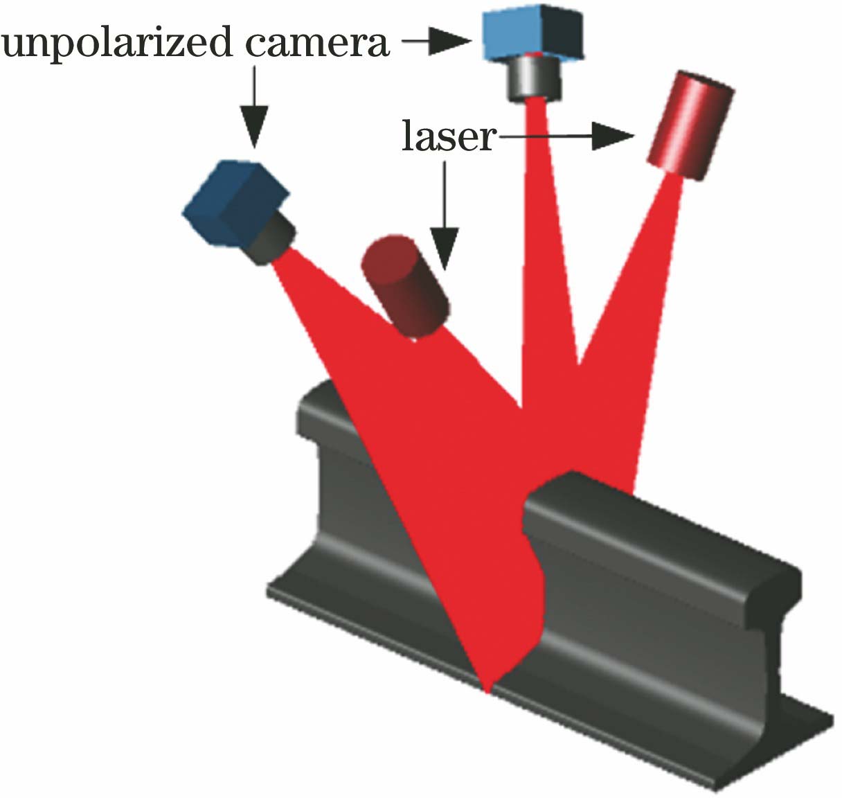
Fig. 1. Principle diagram of line-structured light imaging of rail profile based on traditional unpolarized camera
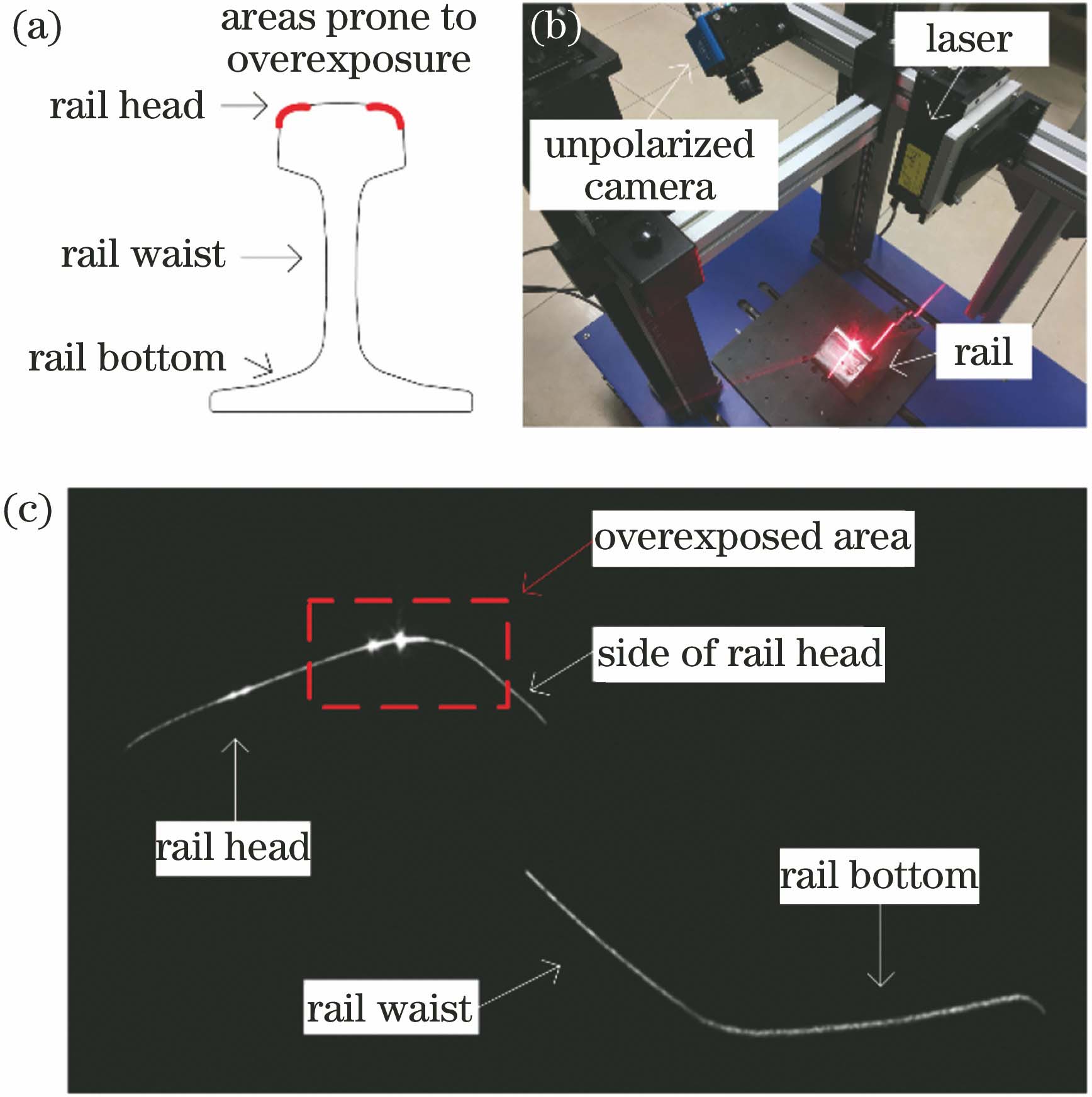
Fig. 2. Local overexposure of rail laser section image. (a) Areas prone to overexposure; (b) image acquisition device; (c) local overexposure image
Fig. 3. Center of light strip in the overexposed area of rail laser section image
Fig. 4. Schematic diagram of rail profile detection based on polarization imaging
Fig. 5. Polarization filter and pixel distribution of polarization camera
Fig. 6. Polarization component images of rail laser section. (a) 0° directional polarization component image; (b) 135° directional polarization component image; (c) 45° directional polarization component image; (d) 90° directional polarization component image
Fig. 7. Width of light strip in each column of rectangular areas in Fig. 2 and Fig. 6
Fig. 8. Flowchart of image fusion algorithm
Fig. 9. Experimental setup for polarization characteristics of rail laser section image
Fig. 10. 0° and 90° directional polarization component images
Fig. 11. Polarization angle distribution in rectangular region
Fig. 12. Image fusion weights in rectangular areas in Fig. 2 and Fig. 6
Fig. 13. Fusion image F
Fig. 14. Light strip center of fusion image
Fig. 15. Measurement errors of rail profile by our method and traditional method
|
Table 1. Degree of polarization of six rectangular regions

Set citation alerts for the article
Please enter your email address
© Copyright 2018-2021 | Chinese Laser Press. All Rights Reserved 沪ICP备15018463号-20