• Chinese Journal of Lasers
  • Vol. 48, Issue 22, 2202003 (2021)
Xiaming Chen1,2, Xiaonan Wang1,*, Qipeng Dong1,2, Zhen Zhu1,2, and Nagaumi Hiromi1,2
Author Affiliations
  • 1School of Iron and Steel, Soochow University, Suzhou, Jiangsu 215021, China
  • 2High-Performance Metal Structural Materials Research Institute, Soochow University, Suzhou, Jiangsu 215021, China
  • show less
    DOI: 10.3788/CJL202148.2202003 Cite this Article Set citation alerts
    Xiaming Chen, Xiaonan Wang, Qipeng Dong, Zhen Zhu, Nagaumi Hiromi. Effect of Filling Material with Different Si Content on Microstructure and Properties of Laser-CMT Aluminum Alloy Joints[J]. Chinese Journal of Lasers, 2021, 48(22): 2202003 Copy Citation Text show less
    Schematic of laser-CMT welding
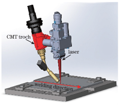
    Fig. 1. Schematic of laser-CMT welding
    Microstructure and grain morphologies of weld center. (a)(c) Al-Si5; (b)(d) Al-Si10
    Fig. 2. Microstructure and grain morphologies of weld center. (a)(c) Al-Si5; (b)(d) Al-Si10
    Grain size and thermal conductivity of weld seam. (a) Grain size; (b) thermal conductivity
    Fig. 3. Grain size and thermal conductivity of weld seam. (a) Grain size; (b) thermal conductivity
    KAM maps and KAM distribution of weld seam. (a) Al-Si5; (b) Al-Si10; (c) KAM distribution
    Fig. 4. KAM maps and KAM distribution of weld seam. (a) Al-Si5; (b) Al-Si10; (c) KAM distribution
    Mircrohardness distribution of welded joints and comparison between microhardness of weld seams. (a) Microhardness distribution of welded joints; (b) comparison between microhardness of weld seams
    Fig. 5. Mircrohardness distribution of welded joints and comparison between microhardness of weld seams. (a) Microhardness distribution of welded joints; (b) comparison between microhardness of weld seams
    Macroscopic morphology of welded joint and stress-strain curve. (a) Macroscopic morphology; (b) engineering stress-strain curve; (c) fracture morphology
    Fig. 6. Macroscopic morphology of welded joint and stress-strain curve. (a) Macroscopic morphology; (b) engineering stress-strain curve; (c) fracture morphology
    Yield strength and its increment of the two welds
    Fig. 7. Yield strength and its increment of the two welds
    Droplet transfer and keyhole morphology. (a) Current waveform; (b) stage B amplification; (c) droplet transfer and keyhole morphology
    Fig. 8. Droplet transfer and keyhole morphology. (a) Current waveform; (b) stage B amplification; (c) droplet transfer and keyhole morphology
    MaterialSiMgFeMnCrCuZnTiAl
    Base metal1.00.70.10.6<0.1<0.1<0.1<0.11Bal.
    Al-Si55.0<0.10.2<0.1<0.1<0.1<0.1<0.1
    Al-Si1011.0<0.10.2<0.1<0.1<0.1<0.1<0.1
    Table 1. Mass fraction of chemical compositions of base metal and filling materials unit: %
    Filling materialPhaseSiMgFeMnAlPossible phase
    Al-Si5White phase6.400.71.702.00Bal.AlFeSi
    11.302.100.80Eutectic Si
    α-Al0.350.30α-Al
    Al-Si10White phase9.601.304.704.10Bal.AlFeSi
    11.102.401.60Eutectic Si
    α-Al0.600.30α-Al
    Table 2. Element mass fraction of EDS analysis of weld microstructure unit: %
    Filling materialSiMgFeMnCrCuZnTiAl
    Al-Si51.460.500.150.42<0.01<0.01<0.010.02Bal.
    Al-Si102.340.500.150.42<0.01<0.01<0.010.02
    Table 3. Mass fraction of chemical composition of weld seam with different filling materials unit: %
    ParameterAl-Si5Al-Si10
    KAM /℃0.5640.557
    ρ /m-22.16×10122.14×1012
    Table 4. KAM and dislocation density of both welds
    Xiaming Chen, Xiaonan Wang, Qipeng Dong, Zhen Zhu, Nagaumi Hiromi. Effect of Filling Material with Different Si Content on Microstructure and Properties of Laser-CMT Aluminum Alloy Joints[J]. Chinese Journal of Lasers, 2021, 48(22): 2202003
    Download Citation