• Photonics Research
  • Vol. 5, Issue 5, 481 (2017)
Li-Guo Qin1、2、*, Zhong-Yang Wang2、3, Shang-Qing Gong4, and Hong-Yang Ma1
Author Affiliations
  • 1School of Science, Qingdao University of Technology, Qingdao 266000, China
  • 2Shanghai Advanced Research Institute, Chinese Academy of Sciences, Shanghai 201210, China
  • 3e-mail: wangzy@sari.ac.cn
  • 4Department of Physics, East China University of Science and Technology, Shanghai 200237, China
  • show less
    DOI: 10.1364/PRJ.5.000481 Cite this Article Set citation alerts
    Li-Guo Qin, Zhong-Yang Wang, Shang-Qing Gong, Hong-Yang Ma. Electro-optic waveform interconnect based on quantum interference[J]. Photonics Research, 2017, 5(5): 481 Copy Citation Text show less
    Proposed opto- and electro-mechanical hybrid system composed of a tunable cavity with a charged mirror operating as a CMO and a mechanically variable capacitor. A Λ-type three-level medium confined inside the cavity interacts with two optical fields: a constant optical field ϵc, which is resonantly injected into the cavity along the x axis to form the cavity field, and the probe field Ep, which is externally injected into the cavity along the z axis at frequency ωp.
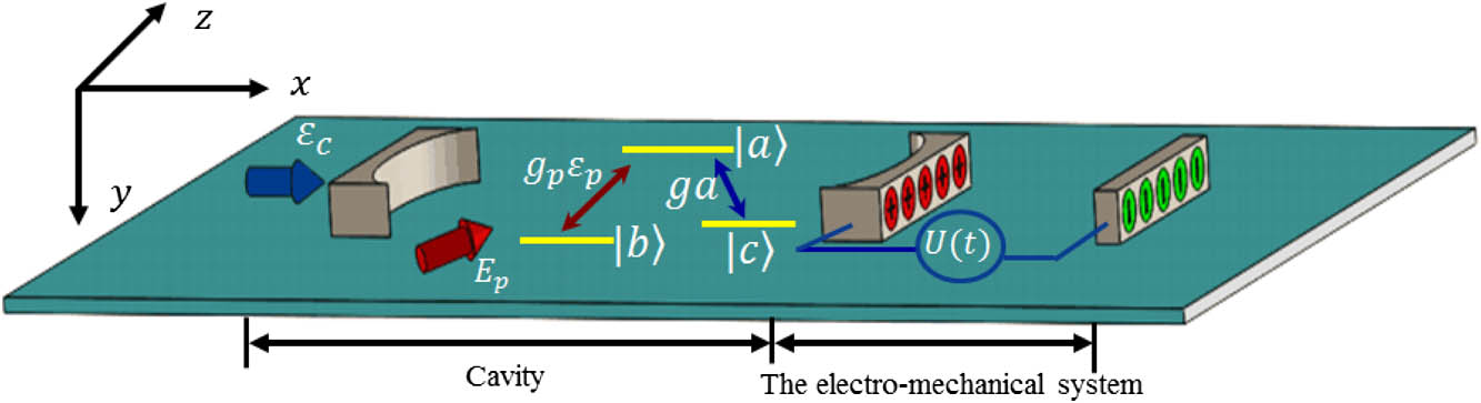
    Fig. 1. Proposed opto- and electro-mechanical hybrid system composed of a tunable cavity with a charged mirror operating as a CMO and a mechanically variable capacitor. A Λ-type three-level medium confined inside the cavity interacts with two optical fields: a constant optical field ϵc, which is resonantly injected into the cavity along the x axis to form the cavity field, and the probe field Ep, which is externally injected into the cavity along the z axis at frequency ωp.
    Imaginary part of the susceptibility of the probe field in the medium as a function of the square of the voltage U2 and the detuning Δp. The inset shows the real part of the susceptibility. Here, the units of the voltage and the detuning axis are the square of the voltage (V2) and hertz (Hz), respectively. The parameters are used from the experiments in Ref. [32] as ϵc=4×10¹⁰ Hz, γ=2π×5.75 MHz, γs=0.0001γ, g=0.001γ, κ=0.2γ, ωm=γ, m=145 ng, G0=2π×1.5×1016 Hz/m, S=0.6 mm2, r=0.21 μm, δ=0, and atomic density ∼1019 m−3. The modulative material is Rb87 with Λ-type three-level configuration.
    Fig. 2. Imaginary part of the susceptibility of the probe field in the medium as a function of the square of the voltage U2 and the detuning Δp. The inset shows the real part of the susceptibility. Here, the units of the voltage and the detuning axis are the square of the voltage (V2) and hertz (Hz), respectively. The parameters are used from the experiments in Ref. [32] as ϵc=4×10¹⁰  Hz, γ=2π×5.75  MHz, γs=0.0001γ, g=0.001γ, κ=0.2γ, ωm=γ, m=145  ng, G0=2π×1.5×1016  Hz/m, S=0.6  mm2, r=0.21  μm, δ=0, and atomic density 1019  m3. The modulative material is Rb87 with Λ-type three-level configuration.
    Numerical results of the EOM. (a) Modulation of the sine wave: (a1) shows the target absorptive waveform and numerical results, and (a2) shows the square of voltage waveform U2 applied to the capacitor. (b) Modulation of the sawtooth wave: (b1) shows the target absorptive waveform and numerical results, and (b2) shows the square of voltage waveform U2 applied to the capacitor. (c) Modulation of the square wave: (c1) shows the target absorptive waveform and numerical results, and (b2) shows the square of voltage waveform U2 applied to the capacitor. The simulation parameters are ϵc=0.5×10¹⁰ Hz, γm=3γ, and κ=0.4γ; the other parameters are the same as in Fig. 2.
    Fig. 3. Numerical results of the EOM. (a) Modulation of the sine wave: (a1) shows the target absorptive waveform and numerical results, and (a2) shows the square of voltage waveform U2 applied to the capacitor. (b) Modulation of the sawtooth wave: (b1) shows the target absorptive waveform and numerical results, and (b2) shows the square of voltage waveform U2 applied to the capacitor. (c) Modulation of the square wave: (c1) shows the target absorptive waveform and numerical results, and (b2) shows the square of voltage waveform U2 applied to the capacitor. The simulation parameters are ϵc=0.5×10¹⁰  Hz, γm=3γ, and κ=0.4γ; the other parameters are the same as in Fig. 2.
    Li-Guo Qin, Zhong-Yang Wang, Shang-Qing Gong, Hong-Yang Ma. Electro-optic waveform interconnect based on quantum interference[J]. Photonics Research, 2017, 5(5): 481
    Download Citation