Abstract
The ability to modulate an optical field via an electric field is regarded as a key function of electro-optic interconnects, which are used in optical communications and information-processing systems. One of the main devices required for such interconnects is the electro-optic modulator (EOM). Current EOMs based on the electro-optic and electro-absorption effects often are bulky and power-inefficient due to the weak electro-optic properties of their constituent materials. Here, we propose a new mechanism to produce an arbitrary-waveform EOM based on quantum interference, in which both the real and imaginary parts of the susceptibility are engineered coherently with super-high efficiency. Based on this EOM, a waveform interconnect from the voltage to the modulated optical absorption is realized. We expect that such a new type of electro-optic interconnect will have a broad range of applications, including in optical communications and networks.1. INTRODUCTION
The trend toward on-chip and off-chip photonics has lasted for decades [1–3]. Current integrated silicon photonics technology can support the design of electronics and photonics on the same chip and enable cost-efficient optical links that connect racks, modules, and chips together [3,4]. This indicates the beginning of an era of chip-scale electronic-photonic systems [4]. However, to realize electro-optic interconnect, the electro-optic chip faces challenges including electro-optic transformation and low power consumption [1]. Moreover, the synchronous interconnect of the electro-optic signals meets difficulties in matching the propagation velocity, high modulation capability, and response speed. The electro-optic modulator (EOM) is a device that potentially can perform the main required functions of this electro-optic interconnection and realize the dynamical transformation from electrical to optical signals.
In an EOM, the modulation of the optical field is primarily subject to the electro-optic properties of the medium [5]. For EOMs based on the electro-optic effect, the refractive index , i.e., the real part of the material susceptibility, is proportional to the electric field (Pockels effect) or the square of the electric field (Kerr effect) [6]. Although these well-studied effects have been exploited in numerous EOM devices, they require large components and/or a high driving voltage owing to the weakness of the electro-optic effect [7] (e.g., for the Pockels effect in and for the Kerr effect in silicon with an applied field of [6]). These requirements lead to higher energy dissipation than appropriate for off- or on-chip interconnection [8].
Electro-absorption effects are another modulation mechanism in which the absorption spectra are modified by the applied electric field. Electro-absorption effects include the Franz–Keldysh effect [9] in bulk semiconductor materials and the quantum-confined Stark effect [10] in quantum well structures [7,11]; these effects originate from the distortion of the energy bands by an applied electric field, which causes the modification of the absorption coefficient [6]. EOMs based on the electro-absorption effects, which typically involve III–V direct-bandgap semiconductors, are compatible with semiconductor technology [7], which lends itself to the development of compact devices with low power consumption [12,13]. For on-chip integration and miniaturization, silicon-based EOMs are more desirable [14]; however, their development is hampered by the weak electro-optic absorption effect of the indirect bandgap of silicon [15]. Thus, a key area of EOM-related research is the investigation of novel materials with good electro-optic properties such as a graphene-based broadband optical modulator; this has several distinctive advantages, including strong light–graphene interaction, high-speed operation, and CMOS compatibility [16,17]. The high-performance GeSi electro-absorption modulator, with its ultra-low energy consumption, offers unique advantages for use in high-performance electronic–photonic integration with CMOS circuits [7,11]. Here, we report a new modulation mechanism for EOMs based on quantum interference, in which the refractive index and absorption of the material are engineered coherently with unprecedented efficiency [18].
Sign up for Photonics Research TOC. Get the latest issue of Photonics Research delivered right to you!Sign up now
Quantum interference between two excitation pathways of the internal quantum states of a coherent three-level medium has given us the unique capability to engineer the linear and nonlinear susceptibility of the medium. In the case of electromagnetically induced transparency (EIT) [19], when the two metastable states couple to a common excited state by the control and probe fields, the absorption of the probe field in the medium is largely modified through the destructive quantum interference of the amplitudes of the two optical transitions. The width of the transparency window and the steepness of the refractive index curves are modulated over a wide range by dynamically changing the strength of the control field [18]. This ability to modify the susceptibility has revealed many new phenomena in quantum optics, such as ultra-slow group velocities [20] and the storage of light and quantum memory [21]. Furthermore, this feature has been shown experimentally to be able to decrease the group velocity of light by many orders of magnitude [22]. With the slowing of light, nonlinear optics can extend to the few-photon level [23,24].
An optical switch based on quantum interference was proposed by Harris and Yamamoto in a four-level EIT atomic system [25]. Subsequently, this optical switching mechanism was experimentally demonstrated in a four-level atomic system [26]. In 2011, researchers observed that the transmission of the probe field can be perfectly switched using cavity EIT and by applying a weak switching field [27]. These results demonstrate the ability of quantum interference to modulate an optical field.
Photons are the fastest and most robust information carriers. As such, the interconnects used in data communication systems and in long links will gradually change from electrical-based to light-based. However, photons must be slowed down to match the speed of the slow electrons in the electro-optic interconnect. Based on cavity-induced transparency, we previously proposed an approach to realize the electrical manipulation of the dark-state polariton and the group velocity of light [28]. Here, we propose a hybrid EOM system composed of a high-quality tunable cavity and an electro-mechanical system. By the interaction between a three-level medium confined inside the cavity and two optical fields, the group velocity of the modulated optical field in the medium is electrically slowed to match the slow electric signal. Through the use of electrically driven quantum interference, we establish a one-to-one correspondence between the waveforms of the electrical signal and the optical field (that is, to create an electro-optic waveform interconnect) and use it to produce an arbitrary waveform optical field. To the best of our knowledge, this work represents the first proposed electro-optic waveform interconnect based on such an approach.
2. MODEL AND METHOD
Specifically, our scheme proposes implementing a coherent three-level medium that is confined in a compact device composed of a tunable cavity with a high quality factor and an electro-mechanical system, as shown in Fig. 1. The cavity consists of a moveable mirror, which is charged to operate as a charged mechanical oscillator (CMO), and a fixed mirror. The CMO has positive charge , and capacitively couples to a fixed conductive plate that is supplied with negative charge by a voltage waveform with the time regime from a waveform generator. Thus, the CMO and the fixed conductive plate form a mechanically variable capacitor.
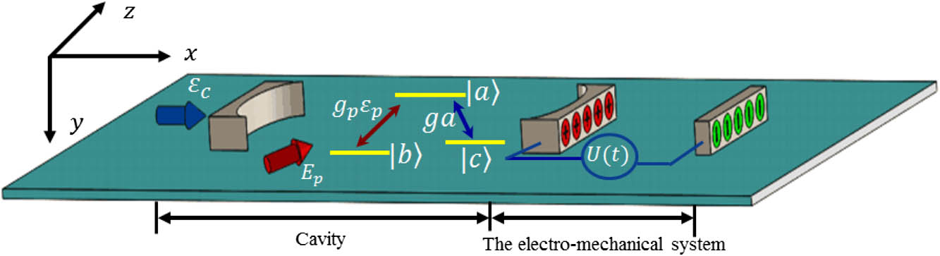
Figure 1.Proposed opto- and electro-mechanical hybrid system composed of a tunable cavity with a charged mirror operating as a CMO and a mechanically variable capacitor. A -type three-level medium confined inside the cavity interacts with two optical fields: a constant optical field , which is resonantly injected into the cavity along the axis to form the cavity field, and the probe field , which is externally injected into the cavity along the axis at frequency .
In this model, the control field injected into the cavity is a constant optical field with an amplitude , where the parameters represent respectively the frequency , power , Planck constant , and cavity decay rate . In this structure, the displacement of the CMO, with a mass and frequency , is driven by the radiation pressure force from the optical field and the Coulomb force from the capacitor. The Coulomb force and the radiation pressure force on the CMO have the same direction and the Coulomb interactions can be approximated as for , where , is the vacuum permittivity, is the voltage, is the area, and is the distance between two capacitive plates [28]. Because of the motion of the CMO, the resonance frequency in the cavity is modified as , where the high-order terms are neglected [29]. This process can lead to a detuning between the cavity field [ () is the the annihilation (creation) operator of the photons in the cavity] and the control field, , which induces the leakage of photons in the cavity. The dynamical equations of the CMO and the cavity field are given by where is the damping rate of the CMO, is the photon number in the cavity, and is the opto- and electro-mechanical coupling strength for a cavity of length [29]. When , where is the displacement of the CMO driven by the radiation pressure force, can be neglected in our model, and therefore the motion of the CMO only depends on the Coulomb force. Below indicates only the cavity detuning driven by the Coulomb force. When the charges are slowly injected into the capacitor with a duration that satisfies and , the evolution of the displacement of the CMO and the cavity field can be considered adiabatically and the solutions of Eq. (1) can be derived as and . When with the maximum cavity detuning , the photon number in the cavity is only controlled by the voltage. Therefore, to electrically switch on or off the cavity field, the decay of the cavity must satisfy . In addition, we can define the effective cavity decay rate as and quality factor of the cavity as , which is dynamically modulated by changing the voltage on the capacitor.
To realize the modulation of a probe field by the voltage, i.e., EOM, an interactive medium with a three-level configuration must be confined at an antinode of the standing wave inside the cavity, in which the probe field couples with the atomic dipole transition between levels and with a coupling strength and detuning ; and the quantized cavity field couples the atomic dipole transition between levels and with a coupling strength and detuning . We assume that the probe field propagates in a direction perpendicular to that of the cavity field. The amplitude of the cavity field at this antinode depends only on time. Here we choose an ensemble of identical -type cold atoms with a volume that interacts with the probe field and cavity field, as shown in Fig. 1; however, any types of EIT media can be used such as the type or ladder type. The interaction Hamiltonian of the system is given by , where are the slowly varying collective operators of the atomic ensemble.
The dynamic equations of the system can be simplified with the slowly varying amplitude and weak-field approximations [21]. We then introduce the dimensionless slowly varying field amplitude and assume that almost all atoms are in the ground state , and that the number of probe photons is considerably smaller than the number of atoms, i.e., (the weak-field approximation). Considering these approximations and keeping the zeroth-order terms of , we determine that , [30], and that the remaining atomic evolutions and can be derived from where
Here, () is the decay rate of the higher energy level (the metastable state ) to the ground state with . For a sufficiently long time, the solution of Eq. (2) can be generally provided by This yields
Thus the first-order susceptibility of the medium can be derived as , where is the dipole moment of the probe transition. The imaginary part of this susceptibility, , determines the dissipation of the probe field, i.e., absorption, whereas the real part, , determines the refractive index [18]. Equation (5) indicates that the width of the transparency window () and the dispersion of the probe field depend on the intensity of the control field [31], which is regulated by the voltage. In Fig. 2, we observe that the width of the transparency window decreases and even disappears when the voltage increases. In this process, the probe field is gradually absorbed by the medium and can even be completely absorbed with a large voltage. Meanwhile, the slope of the steep dispersion is also significantly modified by the voltage (Fig. 2 inset). Because we use a high-quality-factor cavity and cavity-induced transparency, the strong control field required in conventional EIT [18] has been reduced to an assistant optical field with a low and constant intensity, that is, for the observable features of EIT, provided that the cavity field satisfies . Based on the mechanism of cavity-induced transparency [30], quantum interference can then be manipulated by the electric field in this integrated opto- and electro-mechanical system. In the following, we will show that the absorptive waveform of the modulated probe field has a one-to-one correspondence with the waveform of the voltage.
![Imaginary part of the susceptibility of the probe field in the medium as a function of the square of the voltage U2 and the detuning Δp. The inset shows the real part of the susceptibility. Here, the units of the voltage and the detuning axis are the square of the voltage (V2) and hertz (Hz), respectively. The parameters are used from the experiments in Ref. [32] as ϵc=4×10¹⁰ Hz, γ=2π×5.75 MHz, γs=0.0001γ, g=0.001γ, κ=0.2γ, ωm=γ, m=145 ng, G0=2π×1.5×1016 Hz/m, S=0.6 mm2, r=0.21 μm, δ=0, and atomic density ∼1019 m−3. The modulative material is Rb87 with Λ-type three-level configuration.](/Images/icon/loading.gif)
Figure 2.Imaginary part of the susceptibility of the probe field in the medium as a function of the square of the voltage and the detuning . The inset shows the real part of the susceptibility. Here, the units of the voltage and the detuning axis are the square of the voltage () and hertz (Hz), respectively. The parameters are used from the experiments in Ref. [32] as , , , , , , , , , , , and atomic density . The modulative material is with -type three-level configuration.
Now to simplify the expression of , we assume that the system operators are in the resonant regime, i.e., . The imaginary part of the susceptibility is then given by where . Thus, we obtain an analytic expression of the relationship between the absorption of the medium and the voltage . When , the photon number in the cavity field is maximum, described by , which can induce a probe field transparent in the coherent medium. From Eq. (6), the minimum absorption in the transparency window is given by . In real atomic systems, because the coherence decay rate with the forbidden to transition is nonzero, the transparency is never perfect. When , we can consider that the medium is transparent. When approaches zero for a large voltage, the maximum absorption is . The inverse transformation of the corresponding square of the voltage as a function of can also be easily derived from Eq. (6) as where . From Eqs. (6) and (7), we can find a one-to-one correspondence between the voltage and the absorption of the probe field, that is, the change of the voltage can lead to the modulation of the absorption of the probe field. Therefore, EOM based on the electro-optic absorption is achieved. Using this interconnect, we can generate an arbitrary waveform of the optical field by adjusting the corresponding voltage waveform.
If the change of the cavity field caused by the voltage satisfies the adiabatic conditions described in references [21,30,33], the electrically controlled dark-state polariton and group velocity can be obtained as and [28], where the mixed angle is defined as and depends on the voltage on the capacitor. Therefore, the properties of the dark-state polariton and the group velocity are determined by the voltage. By modulating the voltage, the mixing angle can be changed in the range , which can lead to storing and retrieving the probe field in the medium, and the slowing of the group velocity. Therefore, the absorption rate and the group velocity of the probe field are coherently and simultaneously modulated.
3. RESULTS AND DISCUSSION
To demonstrate the ability of the proposed scheme to modulate the optical field, we give the simulation results of Eqs. (3)–(8) in Ref. [28] with the initial time and ; the other values are zero. For the modulative waveforms, we choose the standard and general sine, sawtooth, and square waveforms as the target waveforms, shown by the solid lines in Figs. 3(a1), 3(b1), and 3(c1). In order to obtain the regular target waveforms, the corresponding voltage waveforms of Figs. 3(a2), 3(b2), and 3(c2) with the amplitude were applied to the capacitor by the waveform generator. Then, without the weak-field and adiabatic approximations, we obtain by using the numerical simulations the corresponding modulated waveforms, indicated by the dashed lines in Figs. 3(a1), 3(b1), and 3(c1). The differences between the target and the numerical results mainly originate from the transient properties of the EIT, which can lead to negative absorption, that is, the transient gain [34,35]. The gains appear in the transparency window of the probe, and therefore the modulation amplitude can be enhanced. Further, the numerical results show that the modulated absorptive sine, sawtooth, and square waveforms all can follow the voltage waveform and that an arbitrary-waveform modulator can be produced based on our approach.
Figure 3.Numerical results of the EOM. (a) Modulation of the sine wave: (a1) shows the target absorptive waveform and numerical results, and (a2) shows the square of voltage waveform applied to the capacitor. (b) Modulation of the sawtooth wave: (b1) shows the target absorptive waveform and numerical results, and (b2) shows the square of voltage waveform applied to the capacitor. (c) Modulation of the square wave: (c1) shows the target absorptive waveform and numerical results, and (b2) shows the square of voltage waveform applied to the capacitor. The simulation parameters are , , and ; the other parameters are the same as in Fig. 2.
The extinction ratio (also known as the modulation depth) is used to describe the modulation efficiency of the transmitted light and is defined as the ratio of the maximum transmission to the minimum transmission , in other words [14]. To measure the efficiency of the electrically controlled absorption, we can define the extinction ratio as where the maximum absorption is obtained without the cavity field when the voltage is maximum; the minimum absorption corresponds to the strongest cavity field, which is obtained when the voltage is zero. From Eq. (6), the extinction ratio is calculated as , where corresponding with the maximum detuning . Therefore, we can enhance the extinction ratio by increasing the difference between and . When , the extinction ratio can be reduced as , which is determined by the maximum number of photons in the cavity.
The bandwidth and speed of the modulation are determined by the switching of EIT, however, which is driven by the voltage from the capacitor. The switching time of EIT is subjected to the change of the cavity field in the transient EIT. In the nonadiabatic regime where the control field is switched on in a time that is short compared with the relaxation times (), the transient EIT shows that by increasing the intensity of the control field (or EIT width), the rise and fall times of the transient absorption of the probe can be reduced [34,36,37]. This property has been demonstrated in the absorptive switch in the four-level EIT system based on quantum interference [25,26]. In our scheme, the EIT width depends on the voltage, as shown in Fig. 2. For the nonadiabatic case, the change of the cavity field is determined by the motion of the CMO, which can follow the change of the voltage waveform in the case of the critical or over-damping motion , i.e., the natural response (the transient portion) of the CMO is damped quickly, whereas the forced response (the steady-state portion) wholly depends upon the driving force [38,39]. Therefore, the EIT can be always switched by the voltage. By the numerical simulation we find that, when the diving frequency is comparable to or approaches , EOM still can be realized and the bandwidth is determined by the driving voltage pulse.
In the proposed scheme, it is a key mechanism that the absorption rate in the EIT can be modulated by controlling electrically the control field based on quantum interference, and therefore any coherent medium with an energy level configuration that enables EIT can serve as the modulation medium. The energy-level configuration can be extended from -type to - and cascade-type three-level systems, even to general - [40] or -type [41] configurations. Moverover, the medium can include a wide range of systems—for example, a semiconductor quantum dot [42] or quantum well [43], etc.
Compared to conventional EOM technology, which is based on the electro-optic properties of the constituent materials, our proposed use of a quantum-interference-based EOM to form electric-optic interconnect offers a number of advantages. First, the steep EIT-induced dispersion can lead to a modification of the refractive index over a wide range and even change the refractive index from positive to negative [44,45]. Second, the absorption rate can be greatly modulated by adjusting the transparency window, in which the complete absorption and transparency can be switched. Third, in the process of the coherent interaction, the refractive index and absorption rate are modulated simultaneously. Fourth, in principle, the proposed scheme can overcome the dependence of conventional EOMs on the electro-optic properties of materials.
4. CONCLUSIONS
In summary, we propose a new mechanism to realize an electro-optic waveform interconnect by EOM based on quantum interference. The proposed new mechanism may open a new field to study EOM and waveform transfer from electrical to optical signals. As the quantum interference mechanism is one of the cores of quantum information, the electro-optic modulation (especially the electro-optic waveform transfer) may be used in photonic modulation at the quantum level. This new mechanism exhibits unprecedented capacity for EOM in waveform electro-optic interconnects and may have potential applications in future communication and signal-processing systems.
Acknowledgment
Acknowledgment. We acknowledge Dr. H. Shen, J. Lu, and Simon-Pierre Gorza for language editing and programming support.
References
[1] C. Batten, A. Joshi, J. Orcutt, C. Holzwarth. Building manycore processor-to-DRAM networks with monolithic CMOS silicon photonics. IEEE Micro, 29, 8-21(2009).
[2] D. A. Miller. Rationale and challenges for optical interconnects to electronic chips. Proc. IEEE, 88, 728-749(2000).
[3] A. Shacham, K. Bergman, L. P. Carloni. Photonic networks-on-chip for future generations of chip multiprocessors. IEEE Trans. Comput., 57, 1246-1260(2008).
[4] C. Sun, M. T. Wade, Y. Lee, J. S. Orcutt, L. Alloatti, M. S. Georgas, A. S. Waterman, J. M. Shainline, R. R. Avizienis, S. Lin, B. R. Moss, R. Kumar, F. Pavanello, A. H. Atabaki, H. M. Cook, A. J. Ou, J. C. Leu, Y.-H. Chen, K. Asanović, R. J. Ram, M. A. Popović, V. M. Stojanović. Single-chip microprocessor that communicates directly using light. Nature, 528, 534-538(2015).
[5] C. Huang, R. Lamond, S. K. Pickus, Z. R. Li, V. J. Sorger. A sub-λ-size modulator beyond the efficiency-loss limit. IEEE Photon. J., 57, 2202411(2013).
[6] K. Liu, C. R. Ye, S. Khan, V. J. Sorger. Review and perspective on ultrafast wavelength-size electro-optic modulators. Laser Photon. Rev., 9, 172-194(2015).
[7] P. Chaisakul, D. Marris-Morini, M.-S. Rouifed, J. Frigerio, D. Chrastina, J.-R. Coudevylle, X. L. Roux, S. Edmond, G. Isella, L. Vivien. Recent progress in GeSi electro-absorption modulators. Sci. Technol. Adv. Mater., 15, 014601(2014).
[8] D. A. B. Miller. Device requirements for optical interconnects to silicon chips. Proc. IEEE, 97, 1166-1185(2009).
[9] D. A. B. Miller, D. S. Chemla, S. Schmitt-Rink. Relation between electroabsorption in bulk semiconductors and in quantum wells: the quantum-confined Franz-Keldysh effect. Phys. Rev. B, 33, 6976-6982(1986).
[10] D. A. B. Miller, D. S. Chemla, T. C. Damen, A. C. Gossard, W. Wiegmann, T. H. Wood, C. A. Burrus. Band-edge electroabsorption in quantum well structures: the quantum-confined stark effect. Phys. Rev. Lett., 53, 2173-2176(1984).
[11] J. Liu, M. Beals, A. Pomerene, S. Bernardis, R. Sun, J. Cheng, L. C. Kimerling, J. Michel. Waveguide-integrated, ultralow-energy GeSi electro-absorption modulators. Nat. Photonics, 2, 433-437(2008).
[12] A. Liu, R. Jones, L. Liao, D. Samara-Rubio, D. Rubin, O. Cohen, R. Nicolaescu, M. Paniccia. A high-speed silicon optical modulator based on a metal-oxide-semiconductor capacitor. Nature, 427, 615-618(2004).
[13] V. J. Sorger, N. D. Lanzillotti-Kimura, R. M. Ma, X. Zhang. Ultra-compact silicon nanophotonic modulator with broadband response. Nanophotonics, 1, 17-22(2012).
[14] G. T. Reed, G. Mashanovich, F. Y. Gardes, D. J. Thomson. Silicon optical modulators. Nat. Photonics, 4, 518-526(2010).
[15] M. Cardona, F. H. Pollak. Energy-band structure of Germanium and Silicon: the k · p method. Phys. Rev., 142, 530-543(1966).
[16] M. Liu, X. Yin, E. Ulin-Avila, B. Geng, T. Zentgraf, L. Ju, F. Wang, X. Zhang. A graphene-based broadband optical modulator. Nature, 474, 64-67(2011).
[17] R. Yu, V. Pruneri, F. J. G. de Abajo. Resonant visible light modulation with graphene. ACS Photon., 2, 550-558(2015).
[18] M. Fleischhauer, A. Imamoglu, J. P. Marangos. Electromagnetically induced transparency: optics in coherent media. Rev. Mod. Phys., 77, 633-673(2005).
[19] K.-J. Boller, A. Imamolu, S. E. Harris. Observation of electromagnetically induced transparency. Phys. Rev. Lett., 66, 2593-2596(1991).
[20] L. V. Hau, S. E. Harris, Z. Dutton, C. H. Behroozi. Light speed reduction to 17 metres per second in an ultracold atomic gas. Nature, 397, 594-598(1999).
[21] M. Fleischhauer, M. D. Lukin. Dark-state polaritons in electromagnetically induced transparency. Phys. Rev. Lett., 84, 5094-5097(2000).
[22] A. V. Turukhin, V. S. Sudarhanam, M. S. Shahriar, J. A. Musser, B. S. Ham, P. R. Hemmer. Observation of ultraslow and stored light pulses in a solid. Phys. Rev. Lett., 88, 023602(2001).
[23] M. Bajcsy, S. Hofferberth, V. Balic, T. Peyronel, M. Hafezi, A. S. Zibrov, V. Vuletic, M. D. Lukin. Efficient all-optical switching using slow light within a hollow fiber. Phys. Rev. Lett., 102, 203902(2009).
[24] V. Venkataraman, K. Saha, P. Londero, A. L. Gaeta. Few-photon all-optical modulation in a photonic band-gap fiber. Phys. Rev. Lett., 107, 193902(2011).
[25] S. E. Harris, Y. Yamamoto. Photon switching by quantum interference. Phys. Rev. Lett., 81, 3611-3614(1998).
[26] M. Yan, E. G. Rickey, Y. Zhu. Observation of absorptive photon switching by quantum interference. Phys. Rev. A, 64, 041801(2001).
[27] M. Albert, A. Dantan, M. Drewsen. Cavity electromagnetically induced transparency and all-optical switching using ion Coulomb crystals. Nat. Photonics, 5, 633-636(2011).
[28] L. G. Qin, Z. Y. Wang, G. W. Lin, J. Y. Zhao, S. Q. Gong. Electrically controlled quantum memories with a cavity and electro-mechanical system. IEEE J. Quantum Electron., 52, 9300106(2016).
[29] M. Aspelmeyer, T. J. Kippenberg, F. Marquardt. Cavity optomechanics. Rev. Mod. Phys., 86, 1391-1452(2014).
[30] G. Nikoghosyan, M. Fleischhauer. Photon-number selective group delay in cavity induced transparency. Phys. Rev. Lett., 105, 013601(2010).
[31] A. Javan, O. Kocharovskaya, H. Lee, M. O. Scully. Narrowing of electromagnetically induced transparency resonance in a Doppler-broadened medium. Phys. Rev. A, 66, 013805(2002).
[32] S. Gröblacher, K. Hammerer, M. R. Vanner, M. Aspelmeyer. Observation of strong coupling between a micromechanical resonator and an optical cavity field. Nature, 460, 724-727(2009).
[33] M. Fleischhauer, M. D. Lukin. Quantum memory for photons: dark-state polaritons. Phys. Rev. A, 65, 022314(2002).
[34] Y.-Q. Li, M. Xiao. Transient properties of an electromagnetically induced transparency in three-level atoms. Opt. Lett., 20, 1489-1491(1995).
[35] S. R. de Echaniz, A. D. Greentree, A. V. Durrant, D. M. Segal, J. P. Marangos, J. A. Vaccaro. Observation of transient gain without population inversion in a laser-cooled rubidium Λ system. Phys. Rev. A, 64, 055801(2001).
[36] H. X. Chen, A. V. Durrant, J. P. Marangos, J. A. Vaccaro. Observation of transient electromagnetically induced transparency in a rubidium system. Phys. Rev. A, 58, 1545-1548(1998).
[37] S. E. Harris, Z.-F. Luo. Preparation energy for electromagnetically induced transparency. Phys. Rev. A, 52, R928(1995).
[38] K. Aihara, G. Matsumoto, Y. Ikegaya. Periodic and non-periodic responses of a periodically forced Hodgkin-Huxley oscillator. J. Theoret. Biol., 109, 249-269(1984).
[39] S. Gröblacher. Quantum Opto-Mechanics with Micromirrors(2012).
[40] K. Ying, Y. Niu, D. Chen, H. Cai, R. Qu, S. Gong. White light cavity via modification of linear and nonlinear dispersion in an N-type atomic system. Opt. Commun., 342, 189-192(2015).
[41] C. Ding, J. Li, Z. Zhan, X. Yang. Two-dimensional atom localization via spontaneous emission in a coherently driven five-level M-type atomic system. Phys. Rev. A, 83, 063834(2011).
[42] D. Barettin, J. Houmark, B. Lassen, M. Willatzen, T. R. Nielsen, J. Mørk, A.-P. Jauho. Optical properties and optimization of electromagnetically induced transparency in strained InAs/GaAs quantum dot structures. Phys. Rev. B, 80, 235304(2009).
[43] Z. Wang, B. Yu, S. Zhen, X. Wu. Large refractive index without absorption via quantum interference in a semiconductor quantum well. J. Lumin., 134, 272-276(2013).
[44] M. Ö. Oktel, Ö. E. Müstecaplıoğlu. Electromagnetically induced left-handedness in a dense gas of three-level atoms. Phys. Rev. A, 70, 053806(2004).
[45] Q. Thommen, P. Mandel. Electromagnetically induced left handedness in optically excited four-level atomic media. Phys. Rev. Lett., 96, 053601(2006).


