• Chinese Optics Letters
  • Vol. 20, Issue 1, 010602 (2022)
Xiao Chen, Liangjin Huang*, Yi An, Huan Yang, Zhiping Yan, Yisha Chen, Xiaoming Xi, Zhiyong Pan, and Pu Zhou**
Author Affiliations
  • College of Advanced Interdisciplinary Studies, National University of Defense Technology, Changsha 410073, China
  • show less
    DOI: 10.3788/COL202220.010602 Cite this Article Set citation alerts
    Xiao Chen, Liangjin Huang, Yi An, Huan Yang, Zhiping Yan, Yisha Chen, Xiaoming Xi, Zhiyong Pan, Pu Zhou. Spectrally U-shaped profile of beam propagation factor in all-solid photonic bandgap fiber[J]. Chinese Optics Letters, 2022, 20(1): 010602 Copy Citation Text show less
    Relative losses of the 5-m-length fiber. Inset shows the cross section of our multi-resonant fiber.
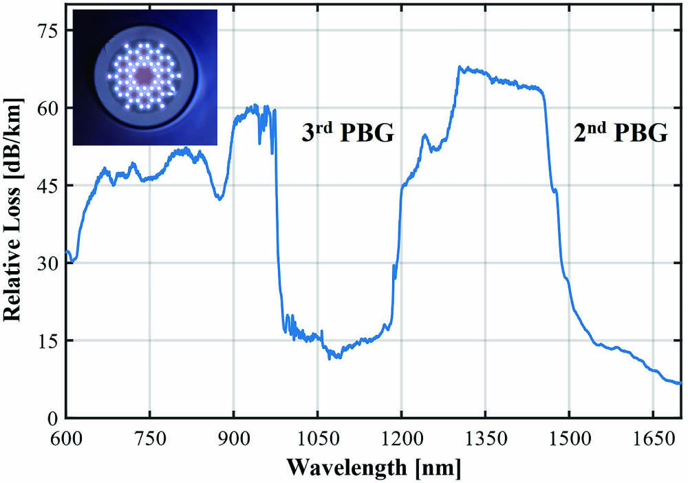
    Fig. 1. Relative losses of the 5-m-length fiber. Inset shows the cross section of our multi-resonant fiber.
    Experimental configurations constructed for (a) M2 and (b) S2 measurements, respectively. SMF, single-mode fiber; FUT, AS-PBGF under test; L, L1, and L2, aspherical lens; M1 and M2, reflective mirror; BQA, beam quality analysis; ASE source, amplified spontaneous emission source; PBS, polarizing beam splitter; CF, collecting fiber; OSA, optical spectrum analyzer.
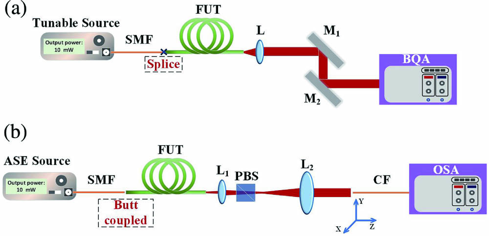
    Fig. 2. Experimental configurations constructed for (a) M2 and (b) S2 measurements, respectively. SMF, single-mode fiber; FUT, AS-PBGF under test; L, L1, and L2, aspherical lens; M1 and M2, reflective mirror; BQA, beam quality analysis; ASE source, amplified spontaneous emission source; PBS, polarizing beam splitter; CF, collecting fiber; OSA, optical spectrum analyzer.
    Measured M2 results under different wavelengths. (a) The U-shaped curve covering the third PBG and (b) partial magnification of the results in the SAE region.
    Fig. 3. Measured M2 results under different wavelengths. (a) The U-shaped curve covering the third PBG and (b) partial magnification of the results in the SAE region.
    S2 data analysis within the NB and LAE regions with a 5-m-length fiber when the coiled diameter Φ = 80 cm.
    Fig. 4. S2 data analysis within the NB and LAE regions with a 5-m-length fiber when the coiled diameter Φ = 80 cm.
    Theoretical calculations of PBGs distribution and beam quality factor M2 based on the measured structural parameters.
    Fig. 5. Theoretical calculations of PBGs distribution and beam quality factor M2 based on the measured structural parameters.
    Theoretical calculations of FM profile and wavefront distribution at 870 nm, 1030 nm, and 1140 nm, respectively.
    Fig. 6. Theoretical calculations of FM profile and wavefront distribution at 870 nm, 1030 nm, and 1140 nm, respectively.
    Beam propagation property of the two representative structures. (a) The “mixed-cell” structure reported in Ref. [18], (b) the “diamond-shaped” scheme proposed in Ref. [17], and (c) calculation results of M2 in their respective PBGs.
    Fig. 7. Beam propagation property of the two representative structures. (a) The “mixed-cell” structure reported in Ref. [18], (b) the “diamond-shaped” scheme proposed in Ref. [17], and (c) calculation results of M2 in their respective PBGs.
    Xiao Chen, Liangjin Huang, Yi An, Huan Yang, Zhiping Yan, Yisha Chen, Xiaoming Xi, Zhiyong Pan, Pu Zhou. Spectrally U-shaped profile of beam propagation factor in all-solid photonic bandgap fiber[J]. Chinese Optics Letters, 2022, 20(1): 010602
    Download Citation