
Honglei Li, Yini Zhang, Xiongbin Chen, Chunhui Wu, Junqing Guo, Zongyu Gao, Hongda Chen. High-speed phosphorescent white LED visible light communications without utilizing a blue filter[J]. Chinese Optics Letters, 2015, 13(8): 080605
- Chinese Optics Letters
- Vol. 13, Issue 8, 080605 (2015)
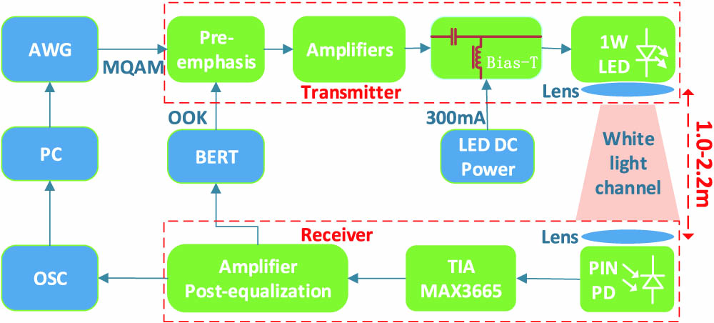
Fig. 1. Experimental setup of the phosphor-based LED VLC system without utilizing a blue filter.
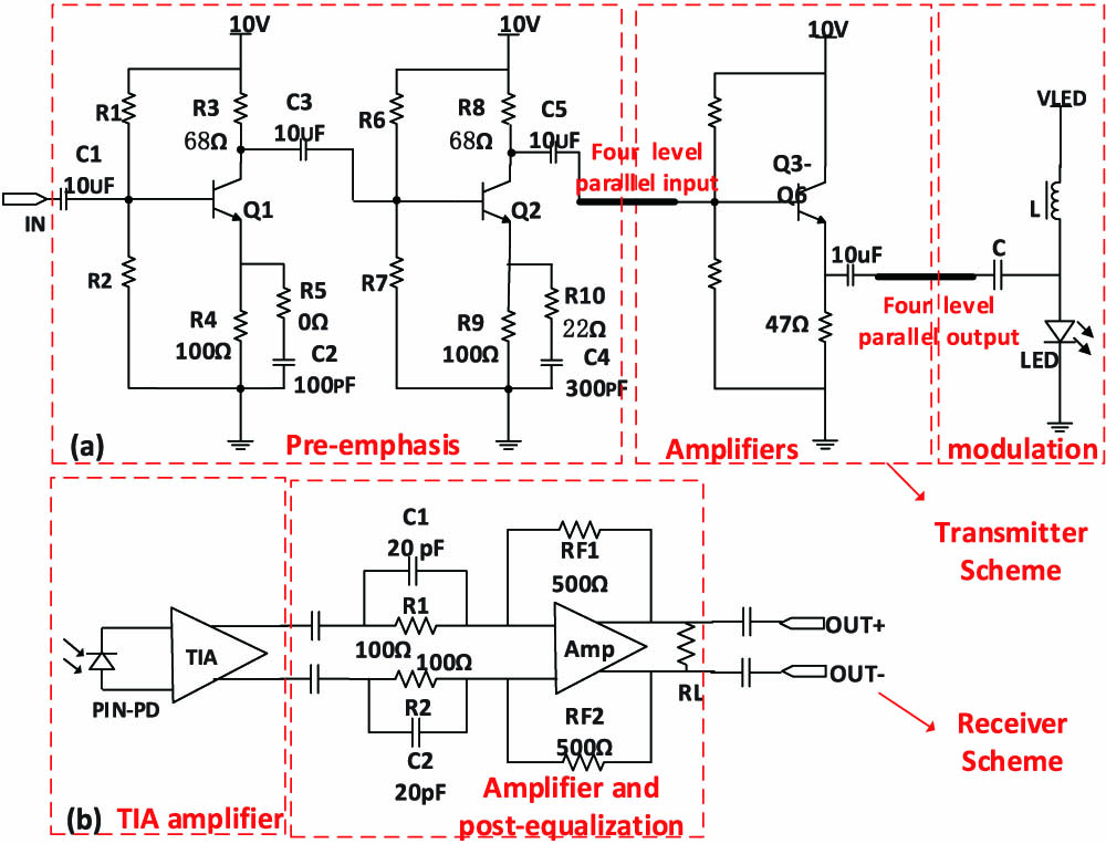
Fig. 2. (a) Transmitter Scheme. (b) Receiver Scheme.
Fig. 3. (a) Experimental phosphor-based white LED VLC link. (b) Designed integrated transmitter module. (c) Designed receiver module.
Fig. 4. EOE system frequency response of the white light, blue light, and yellow component in different cases (with or without PRE and POE).
Fig. 5. BER versus data transmission rate in different cases (white light, white light with PRE, white light with PRE and POE). A BER below 10 − 10
Fig. 6. Measured EVM versus data rate in different cases (without or with PRE and POE) based on the M -QAM scheme. All of the measurements are taken at the distance of 1 m.
Fig. 7. (a) Measured NRZ-OOK transmission data rate, received optical power, and illumination versus radial distance (1, 1.2, 1.4, 1.6, 1.8, 2.0, and 2.2 m). (b) Measured M -QAM (16, 32, and 64-QAM) data transmission rate, EVM and BER versus the radial distance (1, 1.4, 1.8, and 2.2 m).

Set citation alerts for the article
Please enter your email address
© Copyright 2018-2021 | Chinese Laser Press. All Rights Reserved 沪ICP备15018463号-20