Abstract
We experimentally demonstrate a high-speed phosphorescent white light emitting diode (LED) visible light communication (VLC) system without utilizing an optical blue filter. Here, the white light response is equalized by using the proposed analog equalizers. The 3 dB bandwidth of the VLC link could be extended from 3 to 132 MHz, which allows 330 Mbit/s non-return-to-zero on–off keying (NRZ-OOK) data transmission with a bit error ratio (BER) of and 672 Mbit/s 64-quadrature amplitude modulation (64-QAM) data transmission with a BER of . These resultant BERs are less than the forward error correction (FEC) limit of . The VLC link distance is 1 m using a single 1 W LED. The transmitter and receiver modules are integrated to a compact size. Furthermore, the relationships between the signal performance and illumination level or optical power are investigated and analyzed.White light emitting diodes (LEDs) are replacing traditional incandescent lamps and becoming major candidates for future illumination. Visible light communication (VLC) technology based on white LEDs has many attractive advantages, such as high security, immunity to radio frequency interference, worldwide availability and unlicensed bandwidth[1]. VLC could be applied in many areas, such as high-accuracy indoor positioning systems[2–4], high data rate downlink communication in homes and offices[5], and light fidelity (Li-Fi)[6]. VLC is a promising technology for optical wireless communication networks[7] that has been the subject of worldwide research and global standardization efforts[8].
Despite the fact that the 3 dB modulation bandwidths of phosphorescent white LEDs are only a few megahertzs, there are a number of methods, such as blue filtering[9], pre-equalization[10–14], post-equalization (POE)[15,16], sweeping out the remaining carriers[17], spectrally efficient modulation techniques[18–26], and so on that have been reported to enhance the bandwidths and data rates of VLC systems. Since Minh et al. first reported pre-equalization[10] in a VLC system, equalization technologies, including analog and digital equalization[19,26], have been widely used in the area of VLC research.
Sung et al. first explicitly analyzed the function of blue filters[27]. They showed that in the discrete multitones (DMT) VLC system, the blue optical filter may be unnecessary. Yeh et al. demonstrated a 37 Mbit/s real-time white-light phosphor-LED VLC system based on orthogonal frequency division multiplexing (OFDM) modulation without using a blue filter[28]. Yeh et al. demonstrated an adaptive 84.44 to 190 Mbit/s white-light phosphor-LED VLC system based on 16-quadrature amplitude modulation (16-QAM) OFDM modulation scheme utilizing no blue filter[29]. However, they only analyzed and showed DMT or OFDM VLC systems, and introduced little about high-speed on–off keying (OOK) or QAM VLC system without using a blue filter.
Sign up for Chinese Optics Letters TOC. Get the latest issue of Chinese Optics Letters delivered right to you!Sign up now
In our previous work[12], the proposed analog equalizers are designed for a blue light response, not a white light response. In addition, at the transmitter, the pre-emphasis (PRE) circuit, the amplifier, and the bias tee are not integrated together. In this Letter, we optimize analog equalizers for a white light response without utilizing a blue filter. In order to further to reduce the cost and complexity of the VLC link, we integrated PRE, the amplifier, and the self-made bias tee circuits together into a transmitter module. The experiments are further research based on previous work, but the work is not overlapped or repeated.
Here, we experimentally demonstrate a high-speed phosphor-based white LED VLC system. At the receiver, an optical blue filter is not used. The 3 dB bandwidth of the white light response is enhanced to 132 MHz using analog equalizers. Then, the 330 Mbit/s non-return-to-zero (NRZ) OOK data transmission with a bit error ratio (BER) of and 672 Mbit/s 64-quadrature-amplitude-modulation (64-QAM) data transmission with a BER of are achieved. These resultant BERs are less than the forward error correction (FEC) limit of [21,29]. In addition, the relationships between the signal performance and the illumination level or optical power are investigated and analyzed.
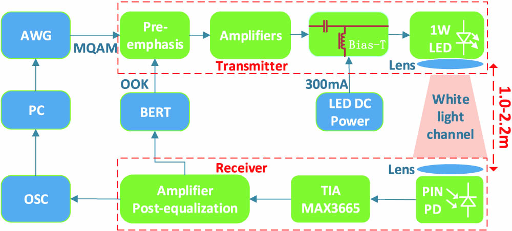
Figure 1 shows the experimental setup of the phosphor-based LED VLC system without utilizing a blue filter. At the transmitter, the input M-QAM format signal generated by an arbitrary waveform generator (AWG, Agilent M8190a) and the input NRZ-OOK signal generated by a BER tester (BERT, Agilent 81250) are processed first by a PRE circuit, then amplified by the amplifiers to enhance the modulation depth. They are then superimposed on the a single 1 W phosphorescent white LED (OSRAM LUW W5AM) by a self-made bias tee circuit. A 10° angle lens is used to focus the LED lights for a longer transmission distance. The DC current of the LED is 300 mA. At the receiver, we do not use an optical blue filter. An optical convex lens (GCL-010217, with a 3 cm focal length) is mounted to collect light into an optical spot in front of the PIN photodiode (HAMAMATSU S10784, 0.3 A/W at 440 nm). A trans-impedance amplifier (TIA) MAX3665 (8 kΩ gain, 470 MHz bandwidth) is used to amplify the electrical current signal of the photodiode, then a differential amplifier (ADA4937-1) circuit with POE boosts the signal level up to the operation range of the BERT. The distance of the phosphor-based white LED VLC link could be operated from 1 to 2.2 m.

Figure 1.Experimental setup of the phosphor-based LED VLC system without utilizing a blue filter.
In Fig. 2, the transmitter and receiver schemes are presented. There are some differences in both the transmitter and receiver compared with those in our previous work[12]. At the transmitter, the amplifiers and bias tee circuits are designed by us using discrete components. The amplifiers are four-level-parallel common collector amplifier circuits. In addition, the PRE, amplifiers, and modulation circuits are integrated together. A limiting amplifier is not used at the receiver in this Letter. Here, we do not place emphasis on how to design the analog equalizers, as reported in Ref. [12]; we just optimize the analog equalizers to equalize the white light response. As opposed to the blue light channel, white light channel equalizers need stronger and higher compensation abilities in a higher frequency region. The typical optimal experimental values of the white light equalization circuits’ key components are shown in Fig. 2.
Figure 2.(a) Transmitter Scheme. (b) Receiver Scheme.
Figure 3(a) shows the experimental VLC link without utilizing a blue filter at a distance of 2 m under an illumination level. At the transmitter, we integrate PRE, amplifiers, and bias tee circuits into a transmitter module with a compact size of , as shown in Fig. 3(b). At the receiver, we also designed a small-size module of that includes POE, as illustrated in Fig. 3(c). The VLC link is low-cost and low-complexity without complex software arithmetic or complicated hardware prototype. We utilize the AWG to generate an M-ary (16, 32, and 64) QAM format signal, and use the real-time oscilloscope to record and save the received QAM format signal from the receiver, then perform the off-line process on a personal computer. However, compared with the off-line signal processing of the M-QAM scheme, the VLC link based on the NRZ-OOK modulation with the help of the BERT could process signal in real time. In the experiment, the carrier frequency of the QAM signal varies with the data rate, and a square root raised cosine filter is utilized to generate the QAM signal.
Figure 3.(a) Experimental phosphor-based white LED VLC link. (b) Designed integrated transmitter module. (c) Designed receiver module.
First of all, we measured the electro-optical-electro (EOE) system frequency response of the white light, blue light, and the yellow component in different cases (with or without PRE and POE), as illustrated in Fig. 4. We define the 3 dB bandwidth as the 3 dB frequency point where the power of the spectral response is reduced by 3 dB compared with the low-frequency reference value[30]. In order to ensure the preciseness and accuracy of the experiment, we set the response of the frequency point at 1 MHz as the low-frequency reference value in all the 3 dB bandwidth measurements in this Letter. Moreover, when we measure the blue and yellow light responses, blue and yellow filters are utilized, respectively. The 3 dB bandwidths of the white light and yellow component are both about 3 MHz, and the bandwidth of the blue light is about 12 MHz. We find that the blue filter only decreases the low frequency and has a smaller influence on the high-frequency white light response. This is due to the fact that the blue filter could filter out the yellow component response, while the yellow light response is higher in the low-frequency than in high-frequency range. Figure 4 shows that when the frequency is higher than 23 MHz, the curves of the blue light and white light responses are overlapped when the VLC link does not contain PRE and POE circuits.
Figure 4.EOE system frequency response of the white light, blue light, and yellow component in different cases (with or without PRE and POE).
Figure 4 also presents the blue light and yellow component responses with the PRE and POE circuits. The PRE and POE circuits enhance both the blue light and yellow component responses, especially in the high frequency region. The white light response can be considered to be the sum of the blue light and yellow component responses. When the frequency changes from 1 to 4 MHz, the yellow response is higher than the blue light response, and when the frequency is higher than 4 MHz, the blue light response is higher than the yellow component. The gap between the blue light and yellow component response grows bigger and bigger as the frequency increases. A bigger gap means that the yellow component has less influence on the white light response. When the frequency is higher than 60 MHz, the curves of blue light and white light responses are nearly overlapped; then, the influence of the yellow component on the white light response can be ignored. Figure 4 also shows that when the VLC link has PRE but no POE circuits, the 3 dB bandwidth of the white light response could be extended from 3 to 85 MHz. When it has both PRE and POE circuits, up to 132 MHz of the 3 dB modulation bandwidth of the white light response can be achieved.
Then, we performed a measurement of the BER and eye diagrams as a function of the data rate in different cases. A pseudo-random binary sequence NRZ-OOK data stream with a peak-to-peak voltage swing of 1 V was set as the input of the transmitter. Figure 5 shows the measured data rates achieved when detecting the white light without equalizers and white light with only PRE circuit are 3 Mbit/s with a BER of and 230 Mbit/s with a BER of . When the VLC link has both PRE and POE circuits, 333 Mbit/s of data transmission can be achieved, and the resultant BER is . All these BER values are less than FEC limit of . Figure 5 also shows that the eye diagrams measured by the wideband oscilloscope (Agilent 86100C) have clear and open eyes at the different rates of 80, 150, 200, 250, and 300 Mbit/s, and that the magnitudes of the eye diagrams are about 600 mV. In general, data rate achieved is not only related to the 3 dB bandwidth of the VLC link, but it also has a relationship with the signal amplitude of the receiver. Figure 5 shows that the channel attenuation closely follows the 3 dB frequency of 132 MHz, and that the remaining elements in the system are guaranteed to have a higher transmission bandwidth up to at least 250 MHz[26], which makes it possible for the VLC link to transmit 330 Mbit/s with only 132 MHz of the 3 dB bandwidth. Furthermore, Fig. 5 shows an abrupt degradation in the BER curves. This is mainly due to clock data recovery losing synchronicity abruptly as the frequency increases.
Figure 5.BER versus data transmission rate in different cases (white light, white light with PRE, white light with PRE and POE). A BER below is truncated to this threshold. Inset: Eye diagram of the VLC system at different data rates (80, 150, 200, 250, and 300 Mbit/s). All of the measurements are taken at the distance of 1 m.
We measured the data rates evaluated according to the measured error vector magnitude (EVM) by using different M-QAM (16, 32, and 64-QAM) modulation signals. The traditional -factor method cannot be simply transferred to the QAM signals. Thus, the EVM method is employed, which could describe the effective distance of the received complex symbol from its ideal position in the constellation diagram. If the received optical field is perturbed by additive white Gaussian noise only, the EVM can be related to the BER. A small EVM leads then to a small BER[31,32]. Figure 6 presents the measured EVM versus the data rate in different cases (with or without PRE and POE) based on the M-QAM modulation scheme. When the VLC link is without PRE and POE circuits, the maximum data rate is 80 Mbit/s with a BER of using the 16-QAM format signal. When the 32-QAM format signal is used without the PRE and POE circuits, then only 75 Mbit/s can be achieved, with a BER of . If we use 64-QAM or an even higher order, the measured data rate is much lower than the above values, which is not shown in Fig. 6. This is due to the fact that the higher-order QAM format signal requires a higher SNR and smaller distance between the adjacent symbols in the constellation diagram. The VLC link without PRE and POE could not meet the requirements of a high-speed 64- or higher-order QAM signal. When the VLC link is operated with PRE and POE circuits, the maximum data rate is 672 Mbit/s with a BER of using a 64-QAM format signal. When PRE and POE circuits are used with 16-QAM and 32-QAM signals, then the data rates are 580 Mbit/s with a BER of and 600 Mbit/s with a BER of , respectively, could be achieved. The proposed PRE and POE circuits are effective in enhancing the data rate of the VLC link based on M-QAM format. This experiment demonstrates that our proposed analog equalizers can be not only used in a simple NRZ-OOK modulation scheme, but that they can also be applied to an advanced modulation format, such as M-QAM.
Figure 6.Measured EVM versus data rate in different cases (without or with PRE and POE) based on the M-QAM scheme. All of the measurements are taken at the distance of 1 m.
In addition, the received optical power, illumination level, OOK data rate, M-QAM (16, 32, and 64-QAM) data rate, EVM and BER versus the radial distance are measured as shown in Fig. 7. It is worth mentioning that the measured received optical power and illumination values in Fig. 7(a) also are appropriated for the M-QAM performance measurements in Fig. 7(b). When the distance of the VLC link is 1 m, the white light illumination level is , the NRZ-OOK transmission data rate is 330 Mbit/s with a BER of , and the 64-QAM data rate is 672 Mbit/s with a BER of and an EVM of 5.62%. When the distance is 1.8 m, the white light illumination level is , which is in agreement with the lighting standard for well-lit working environments[17]. The NRZ-OOK data rate is 323 Mbit/s with a BER of , and the 64-QAM data rate is 510 Mbit/s with a BER of and an EVM of 5%. When the VLC link is as far as 2.2 m, the white light illumination level is 666 lux, the NRZ-OOK data rate is 310 Mbit/s with a BER of , and the 64-QAM data rate is 468 Mbit/s with a BER of and an EVM of 5.15%. All the BERs are below the FEC limit of [21,27].
Figure 7.(a) Measured NRZ-OOK transmission data rate, received optical power, and illumination versus radial distance (1, 1.2, 1.4, 1.6, 1.8, 2.0, and 2.2 m). (b) Measured M-QAM (16, 32, and 64-QAM) data transmission rate, EVM and BER versus the radial distance (1, 1.4, 1.8, and 2.2 m).
A longer distance means lower received optical power and a lower illumination level. When the distance of the VLC link changes from 1 to 1.6 m, the NRZ-OOK data rate is nearly the same, at 330 Mbit/s. This is due to the TIA saturation and non-linearity that appears in the shorter distance cases, which is caused by the limited output of the TIA characteristic. When the distance of the VLC link is longer than 2.2 m, the optical power is lower than 0.258 mW, and then the optical power would be too weak to produce a higher BER and lower data rate. When we measured the VLC link performance utilizing M-QAM signals, we found the data rate decreases as the distance increases from 1 to 2.2 m. This is due to the fact that the M-QAM signals are more sensitive to the received optical power than the NRZ-OOK signals. At the same time, the method to process the received data rate is different. In addition, when we measure the M-QAM data rates at different distances, we adopt nearly the same level of EVM values, for example, 16-QAM with an EVM of , 32-QAM with an EVM of , and 64-QAM with an EVM of . It ensures the accuracy and comparability of the data rates in different cases.
Finally, we evaluate the power consumption of the transmitter. The PRE circuit power consumption is about 0.83 W, the four-parallel-amplifier driver power consumption is about 4.26 W[12], and the LED power consumption is nearly 0.98 W. Therefore, the total theoretical estimated power consumption of the transmitter is about 6.07 W. Most of the power consumption is from amplifier driver consumption. In fact, we sacrifice more power in exchange for a higher bandwidth and longer distance in our proposed VLC system. However, the power consumption can be mostly reduced by optimizing the amplifier drivers.
The above experimental results indicate that the optical blue filter may be unnecessary if equalizers with high equalization abilities are utilized. The main limiting factor to a higher data rate in our experiment is the finite ability of our equalizers. In our next research work, we would improve the performance of the VLC link by designing much more effective analog equalizers.
In conclusion, a high-speed phosphor-based white LED VLC without a blue filter is presented. The 3 dB bandwidth of the white light response is 132 MHz, which is achieved by using optimal analog equalizers. A 330 Mbit/s NRZ-OOK data transmission with a BER of and 672 Mbit/s 64-QAM data transmission with a BER of are achieved. These resultant BERs are less than the FEC limit of . In addition, the VLC link could be operated at different lengths ranging from 1 to 2.2 m. Our proposed VLC system can be operated under the room illumination level of with 323 Mbit/s NRZ-OOK and 510 Mbit/s 64-QAM data transmission. An optical blue filter will be unnecessary for a high-speed VLC link if analog equalizers with high equalization abilities are utilized. Moreover, the transmitter and receiver modules can be designed to be a smaller size while maintaining a high-speed performance.
References
[1] J. Vucic, C. Kottke, S. Nerreter, K. Habel, A. Buttner, K.-D. Langer, J. W. Walewski. Proceedings of OFC/NFOEC, OThH3(2010).
[2] Y. U. Lee, M. Kavehrad. Proceedings of IEEE Photonics Society Summer Topical Meeting Series, 82(2012).
[3] W. Zhang, M. Kavehrad. Proceedings of IEEE Photonics Society Summer Topical Meeting Series, 80(2012).
[4] K. Okuda, S. Oda, T. Nakamura, W. Uemura. Proceedings of IEEE ICCE, 327(2014).
[5] A. Jovicic, J. Li, T. Richardson. IEEE Commun. Mag., 51, 26(2013).
[6] H. Burchardt, N. Serafimovski, D. Tsonev, S. Videv, H. Haas. IEEE Commun. Mag., 52, 98(2014).
[7] H. Elgaga, R. Mesleh, H. Haas. IEEE Trans. Consumer. Electronics, 55, 1127(2009).
[8] K. D. Langer, J. Vucic, C. Kottke, L. F. D. Rosal, S. Nerrete, J. Walewski. Proceedings of ICTON, 90(2009).
[9] J. Grubor, S. C. J. Lee, K.-D. Langer, T. Koonen, J. W. Walewski. Proceedings of ECOC, 1(2007).
[10] H. Le-Minh, D. C. O’Brien, G. Faulkner, L. Zeng, K. Lee, K. Lee, D. Jung, Y. Oh. Proceedings of ECOC, 223(2008).
[11] H. Le-Minh, D. C. O’Brien, G. Faulkner, L. Zeng, K. Lee, K. Lee, D. Jung, Y. Oh. IEEE Photon. Technol. Lett., 20, 1243(2008).
[12] H. Li, X. Chen, J. Guo, H. Chen. Opt. Express, 22, 27203(2014).
[13] H. Li, X. Chen, J. Guo, D. Tang, B. Huang, H. Chen. Chin. Opt. Lett., 12, 100604(2014).
[14] N. Fujimoto, H. Mochizuki. Proceedings of OFC/NFOEC, 73(2013).
[15] H. Le-Minh, D. C. O’Brien, G. Faulkner, L. Zeng, K. Lee, K. Lee, D. Jung, Y. Oh, E. T. Won. IEEE Photon. Technol. Lett., 21, 1063(2009).
[16] H. Li, X. Chen, B. Huang, D. Tang, H. Chen. IEEE Photon. Technol. Lett., 26, 119(2014).
[17] T. Kishi, H. Tanaka, Y. Umeda, O. Takyu. J. Lightwave Technol., 32, 239(2014).
[18] J. Vucic, C. Kottke, S. Nerreter, A. Buttner, K. D. Langer, J. W. Walewski. J. Lightwave Technol., 28, 3512(2010).
[19] A. H. Azhar, T. A. Tran, D. O’brien. IEEE Photon. Technol. Lett., 25, 171(2013).
[20] G. Cossu, A. M. Khalid, P. Choudhury, R. Corsini, E. Ciaramella. Opt. Express, 20, B501(2012).
[21] N. Chi, Y. Wang, Y. Wang, X. Huang, X. Lu. Chin. Opt. Lett., 12, 010605(2014).
[22] Y. Wang, Y. Wang, N. Chi, J. Yu, H. Shang. Opt. Express, 21, 1203(2013).
[23] Y. Wang, X. Huang, J. Zhang, Y. Wang, N. Chi. Opt. Express, 22, 15328(2014).
[24] R. Li, Y. Wang, C. Tang, Y. Wang, H. Shang, N. Chi. Chin. Opt. Lett., 11, 080605(2013).
[25] B. Yu, H. Zhang, H. Dong. Chin. Opt. Lett., 12, 110606(2014).
[26] D. Tsonev, H. Chun, S. Rajbhandari, J. J. D. McKendry, S. Videv, E. Gu, M. Haji, S. Watson, A. E. Kelly, G. Faulkner, M. D. Dawson, H. Haas, D. O’Brien. IEEE Photon. Technol. Lett., 26, 637(2014).
[27] J. Y. Sung, C. W. Chow, C. H. Yeh. Opt. Express, 22, 20646(2014).
[28] C. H. Yeh, Y. L. Liu, C. W. Chow. Opt. Express, 21, 26192(2013).
[29] C. H. Yeh, C. W. Chow, H. Y. Chen, J. Chen, Y. L. Liu. Opt. Express, 22, 9783(2014).
[30] E. F. Schubert. Light-Emitting Diodes(2003).
[31] R. Schmogrow, B. Nebendahl, M. Winter, A. Josten, D. Hillerkuss, S. Koenig, J. Meyer, M. Dreschmann, M. Huebner, C. Koos, J. Becker, W. Freude, J. Leuthold. IEEE Photon. Technol. Lett., 24, 61(2012).
[32] B. Nebendahl, W. Fredude, C. Koos, J. Leuthold, M. Huebner. Proceedings of Electronics, Communications and Photonics Conference (SIECPC), 508(2013).