
Wenbo Guo, Qican Zhang, Zhoujie Wu. Real-Time Three-Dimensional Imaging Technique Based on Phase-Shift Fringe Analysis: A Review[J]. Laser & Optoelectronics Progress, 2021, 58(8): 0800001
- Laser & Optoelectronics Progress
- Vol. 58, Issue 8, 0800001 (2021)
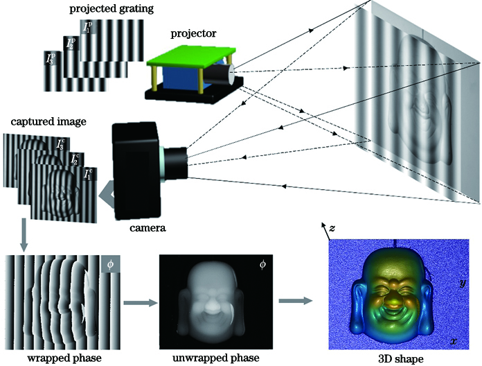
Fig. 1. Schematic of 3D imaging technique based on phase-shift fringe analysis
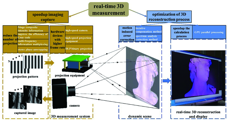
Fig. 2. Main optimization approaches of real-time 3D measurement
Fig. 3. Installation diagram of fast projection equipment. (a) Laser interference fringe measurement system[33]; (b) light source stepping method phase shift projection equipment[34]; (c) array projection equipment[35]; (d) rotating projection measurement system[36]; (e) rotating structured light sequence projection equipment[38]; (f) 5D hyperspectral imaging system[40]; (g) rotating projection measurement system[43]; (h) MEMS galvanometer scanning projection measurement system[45]
Fig. 4. Fringe binarization. (a) Binary fringes; (b) local magnification; (c) binary fringe defocusing effect
Fig. 5. Schematic of phase unwrapping guided by fringe embedding auxiliary information. (a) De Bruijn sequence embedding four-step phase shift fringes[67]; (b) periodic signal embedding four-step phase shift fringes[68]; (c) speckle signal embedding three-step phase shift fringes[69]; (d) phase encoding embedding four-step phase shift fringes[21]
Fig. 6. Gray code aided phase shift technique[72-73]. (a) Projected phase shift fringes; (b) projected Gray code fringes; (c) decoding process of the Gray codes; (d) decoding process of the complementary Gray codes
Fig. 7. Schematic of improving Gray code efficiency. (a) Cyclic complementary Gray code aided phase shift method[74]; (b) shifting Gray code aided phase shift method[75]; (c) regional division phase unwrapping method and Gray code multiplexing coding strategy[76]; (d) ternary Gray code aided phase shift method[77]
Fig. 8. Schematic of multi-frequency fringes information multiplexing. (a) Dual-frequency composite phase shift method[79,8]; (b) 3+2 phase shift method[80,8]; (c) 2+2 phase shift method[81,8]
Fig. 9. Schematic of multi-view stereo phase unwrapping and depth constraint[85]
Fig. 10. Real-time 3D shape measurement and motion error elimination method[100]. (a) Processing flow; (b) 3D reconstruction sequence
Fig. 11. Some results of real-time 3D reconstruction

Set citation alerts for the article
Please enter your email address
© Copyright 2018-2021 | Chinese Laser Press. All Rights Reserved 沪ICP备15018463号-20