
Xiaofeng Shang, Shishuo Li, Zhiguo Wang, Jibin Zhao, Yuhui Zhao, Zhenfeng He, Changwu Nie. Effects of Processing Parameters on Morphology and Microstructure of Plasma Arc Deposition Using 316L Stainless Steel[J]. Laser & Optoelectronics Progress, 2020, 57(1): 011601
- Laser & Optoelectronics Progress
- Vol. 57, Issue 1, 011601 (2020)
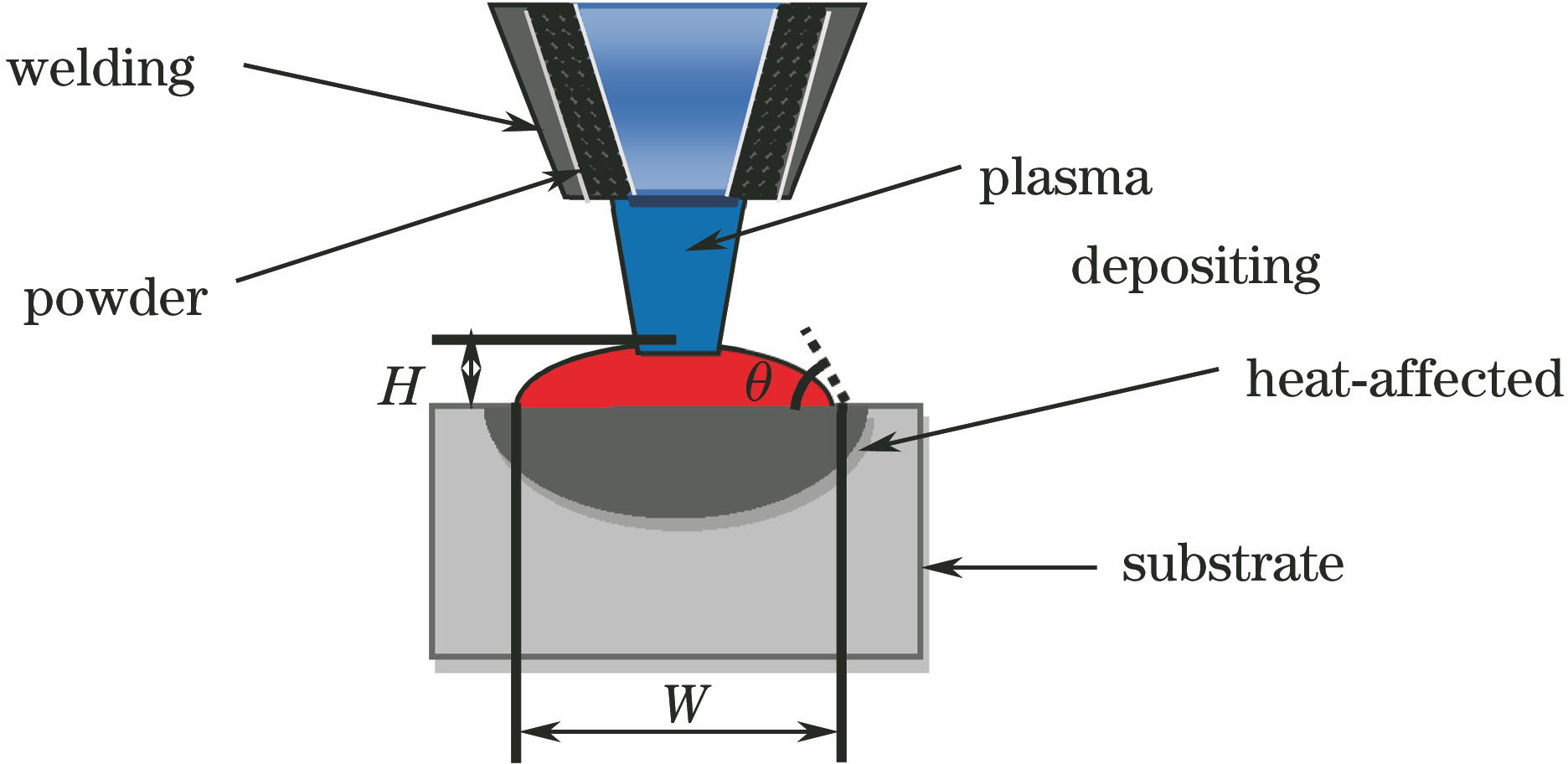
Fig. 1. Schematic of plasma arc deposition with coaxial powder feeding
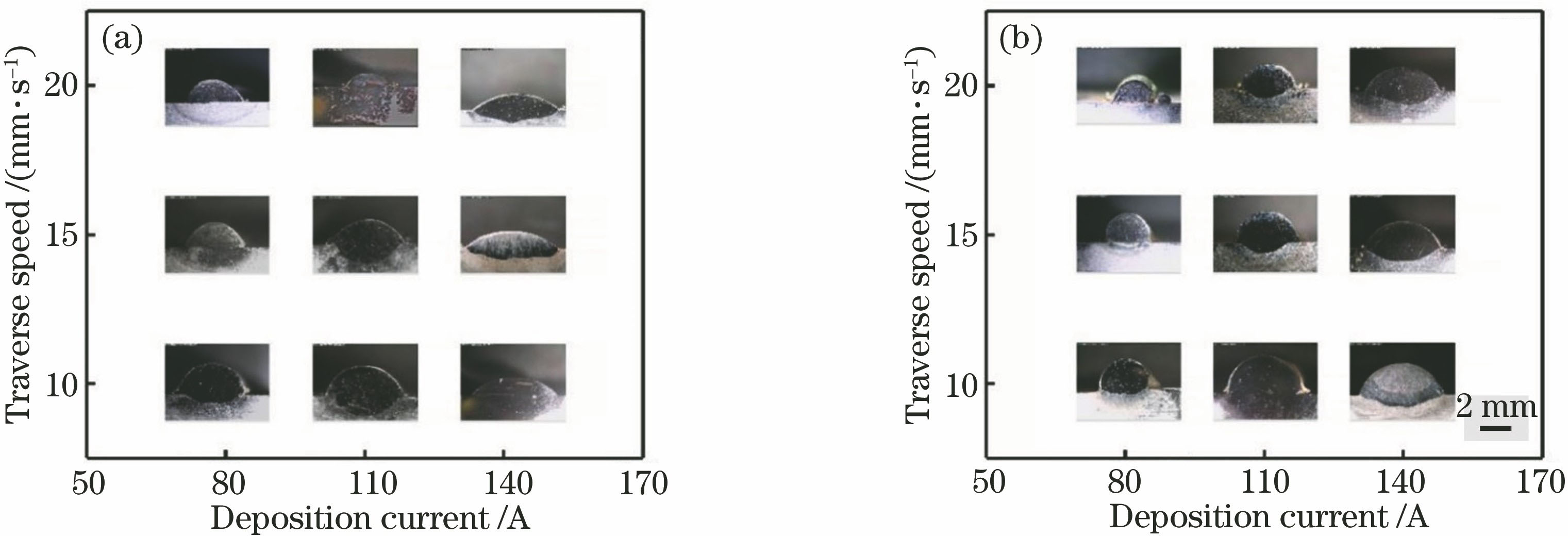
Fig. 2. Macroscopic morphologies of single-track deposited layers with different powder feeding rates. (a) 15 g·min-1; (b) 25 g·min-1
Fig. 3. Dimensions of single-track deposited layers with different process parameters. (a) Deposition width; (b) deposition height
Fig. 4. Schematic of cross section of deposited layer
Fig. 5. Dilution rates of deposited layer with different process parameters. (a) Dilution rates of deposited layer with different scanning speeds; (b) dilution rates of deposited layer with different deposition currents
Fig. 6. Microstructures of 3# deposited specimen. (a) Overall morphology; (b) left section; (c) bottom section; (d) top section
Fig. 7. Microstructures of 16# deposited specimen. (a) Overall morphology; (b) left section; (c) bottom section; (d) top section
Fig. 8. Mass fraction of each element under different energy input
Fig. 9. SEM image of 316L stainless steel after plasma arc deposition
Fig. 10. Microstructures of 3# deposited specimen. (a) Top section; (b) middle section; (c) bottom section
|
Table 1. Chemical compositions of 316L stainless steel powder
|
Table 2. Process parameters of plasma arc deposition
| ||||||||||||||||||||||||||||||||||||||||||
Table 3. Relationship among deposition angle, deposition current, and scanning speed at powder feeding rate of 15 g·min-1
| ||||||||||||||||||||||||||||||||||||||||||||||||||||||
Table 4. Relationship among depositing angle, deposition current, and scanning speed at powder feeding rate of 25 g·min-1

Set citation alerts for the article
Please enter your email address
© Copyright 2018-2021 | Chinese Laser Press. All Rights Reserved 沪ICP备15018463号-20