
Hongxing Niu, Jing Gao, Kaiming Nie. Modeling and Motion Error Analysis of a Time-of-Flight Image Sensor[J]. Laser & Optoelectronics Progress, 2021, 58(24): 2428001
- Laser & Optoelectronics Progress
- Vol. 58, Issue 24, 2428001 (2021)
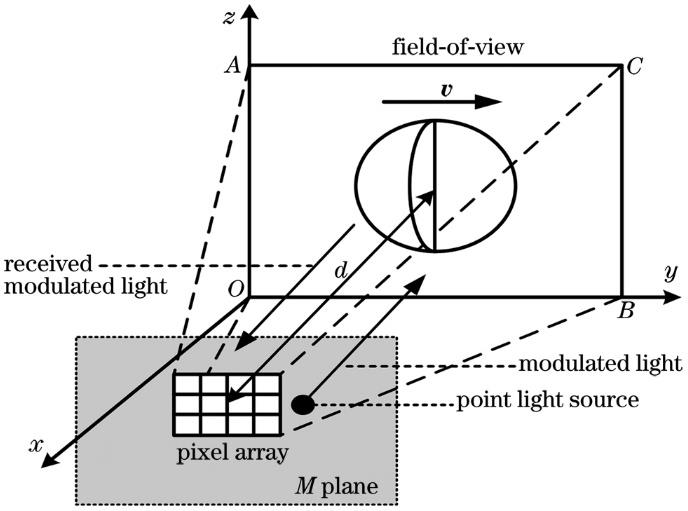
Fig. 1. Conceptual diagram of imaging model of TOF image sensor
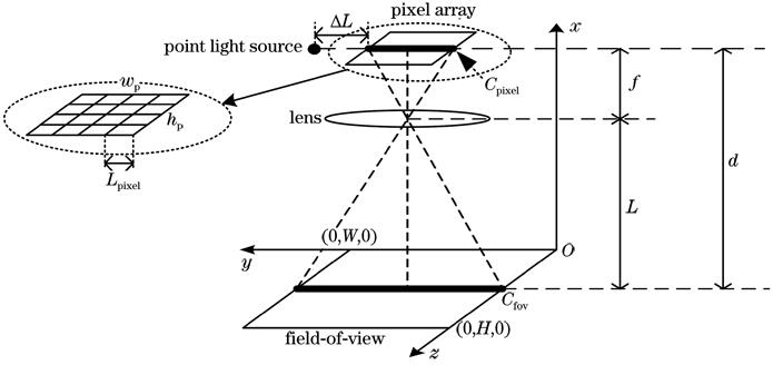
Fig. 2. Optical geometric perspective relationship between pixel array and field-of-view
Fig. 3. Effect before and after adding diffuser. (a) Before adding diffuser; (b) after adding diffuser
Fig. 4. Vector diagram of field-of-view based on the phong model
Fig. 5. Four-phase charge sampling process
Fig. 6. Verification in static scenarios. (a) Comparison of measured and simulated distance data at different imaging distances; (b) RMSE comparison of measured and simulated distance data at different imaging distances
Fig. 7. Measured images and simulated three-dimensional (3D) images. (a) Amplitude image of a wall; (b) measured 3D image of a wall; (c) simulated 3D image of a wall; (d) amplitude image of a hemisphere; (e) measured 3D image of a hemisphere; (f) simulated 3D image of a hemisphere
Fig. 8. Mean pixel error (MPE) between measured and simulated 3D images at different frame rates and speeds. (a) Different frame rates; (b) different speeds
Fig. 9. MPE of two exposure modes at different frame rates and speeds. (a) Global shutter; (b) rolling shutter
Fig. 10. Three-dimensional diagram between MPE difference, frame rate and speed
Fig. 11. Relationship between imaging distance and MPE at the lowest point of imaging condition b
|
Table 1. Parameter settings of model
|
Table 2. Optimal imaging indicator

Set citation alerts for the article
Please enter your email address
© Copyright 2018-2021 | Chinese Laser Press. All Rights Reserved 沪ICP备15018463号-20