
Linhai Xu, Yufei Wang, Yufei Jia, Wanhua Zheng. Research Progress of Low-Coherence Laser[J]. Acta Optica Sinica, 2021, 41(8): 0823008
- Acta Optica Sinica
- Vol. 41, Issue 8, 0823008 (2021)
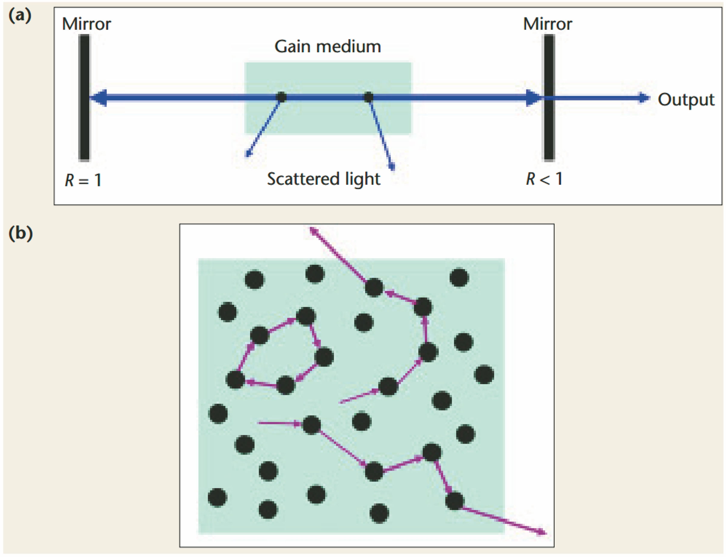
Fig. 1. Comparison of traditional Fabry-Pérot laser and random laser. (a) Schematic of a Fabry-Pérot laser with two mirrors and a gain medium, the right mirror is partially mirror, the black dots represent the scattering center in laser cavity; (b) generation mechanism of random laser, multiple scattering increases the path of light inside the random gain medium
![Electrically-injected random photonic crystal laser[31]. (a) Structure schematic of lateral cavity photonic crystal surface emitting laser; (b) SEM image of random photonic crystal; (c) optical power-current curves of random photonic crystal laser under different Vr(variable of Gaussian distribution random function); (d) emission spectra for Vr=0 nm; (e) emission spectra for Vr=20 nm; (f) emission spectra for Vr=40 nm; (g) emission spectra for Vr=50 nm](/richHtml/gxxb/2021/41/8/0823008/img_2.jpg)
Fig. 2. Electrically-injected random photonic crystal laser[31]. (a) Structure schematic of lateral cavity photonic crystal surface emitting laser; (b) SEM image of random photonic crystal; (c) optical power-current curves of random photonic crystal laser under different Vr(variable of Gaussian distribution random function); (d) emission spectra for Vr=0 nm; (e) emission spectra for Vr=20 nm; (f) emission spectra for Vr=40 nm; (g) emission spectra for Vr=50 nm
Fig. 3. Electrically-pumped random laser with directivity[42]. (a) Schematic of the random laser; (b) SEM picture of a random laser with 25% hole-filling fraction and total resonator diameter of 500 μm, the diameter of the holes is 20 μm; (c) current-voltage (IV) and light power-current (LI) characteristics of devices with various filling fractions, measured at a heat-sink temperature of 5 K; (d) maximum operating temperature and the peak output power measured in the surface direction of the device with different filling fractions
Fig. 4. Experimental device[32]
Fig. 5. Speckle-free full-field imaging[32]. (a) Detected image using small pinhole; (b) detected image using large pinhole
Fig. 6. Schematic of electrically-pumped degenerate cavity laser, controlling the number of modes of degenerate cavity by adjusting the size of the aperture[11]. (a) Large aperture and low coherence operation; (b) small aperture and high coherence operation
Fig. 7. Contour of Xenopus embryonic heart obtained by low coherence light imaging and blood flow in heart of Xenopus embryo under high coherence light[11]. (a) Xenopus embryo with highlighted heart region; (b) heart beating cycle of Xenopus embryo; (c) embryo heart under high-coherence light source; (d)-(f) schematic of heart contours at different stages taken with low-coherence light source; (g)-(i) speckle imaging at different stages taken with high-coherence light source
Fig. 8. Design and simulation of D-shaped cavity laser[34]. (a) Schematic of the D-shaped cavity; (b)-(d) electric field distributions of the highest Q mode; (e) calculated pump thresholds of the first 10 lasing modes
Fig. 9. Spatial coherence of the lasers and application to full-field imaging[34]. (a)(b) Speckle contrast of the F-P cavity laser and D-shaped cavity laser; (c)(d) Air Force Resolution Chart of the F-P cavity laser and D-shaped cavity laser in transmission mode
Fig. 10. Stability diagram of the resonator, unstable resonator systems lie in shaded regions[66]
Fig. 11. Schematic of the quasi-stadium semiconductor laser[68]
Fig. 12. Schematic of the near concentric cavity structure[36]. (a) 2D symmetric stable cavity; (b) spatial intensity profile of a high-order transverse mode in a stable cavity; (c) non-axial mode; (d) three-dimensional sketch of the stable cavity with directional emission
Fig. 13. Simulation results of different resonators[36]. (a) Dependence of quality factor Q on number of transverse mode m; (b) spatial distributions of field amplitude (left) and corresponding Husimi projections (right) for high-order transverse modes (m=7); (c) number of high-Q resonance mode and number of lasing modes as functions of parameter g
Fig. 14. Schematic of dumbbell-shaped cavity. (a) Schematic of the dumbbell-shaped cavity with five-layer structure; (b) SEM image of the dumbbell-shaped cavity, the virtual coil represents the cavity side wall wrapped by SiO2 and metal layer
Fig. 15. Mode field distributions of the five types of typical modes in the dumbbell-shaped cavity[37]. (a) First type of mode; (b) second type of mode; (c) high-Q mode of the third type of mode; (d) low-Q mode of the third type of mode; (e) fundamental F-P mode; (f) concentric cavity mode; (g) hybrid mode; (h) chaotic mode
Fig. 16. Experimental results of the dumbbell-shaped cavity semiconductor laser[37]. (a) Output power and voltage as functions of injection current; (b) emission spectrum; (c) horizontal far-field pattern; (d) speckle pattern; (e) schematic of the experimental setup to characterize speckle contrast
|
Table 1. Parameters of the quasi-stadium resonator[68]

Set citation alerts for the article
Please enter your email address
© Copyright 2018-2021 | Chinese Laser Press. All Rights Reserved 沪ICP备15018463号-20