• Photonics Research
  • Vol. 11, Issue 9, 1500 (2023)
Guang Zhu Zhou1、2, Bao-Jie Chen2, Geng-Bo Wu2, Shi-Wei Qu1、*, and Chi Hou Chan2、3
Author Affiliations
  • 1School of Electronic Science and Engineering, University of Electronic Science and Technology of China (UESTC), Chengdu 611731, China
  • 2State Key Laboratory of Terahertz and Millimeter Wave, City University of Hong Kong, Hong Kong 999077, China
  • 3Department of Electrical Engineering, City University of Hong Kong, Hong Kong 999077, China
  • show less
    DOI: 10.1364/PRJ.485472 Cite this Article Set citation alerts
    Guang Zhu Zhou, Bao-Jie Chen, Geng-Bo Wu, Shi-Wei Qu, Chi Hou Chan. All-plasmonic optical leaky-wave antenna with a low sidelobe level[J]. Photonics Research, 2023, 11(9): 1500 Copy Citation Text show less
    (a) 3D schematic view of the proposed low-sidelobe plasmonic antenna. (b) Cross-section view of a uniform plasmonic gap waveguide. (c) E-field distribution of the plasmonic gap mode. The parameters are w=350 nm, g=200 nm, and t=100 nm.
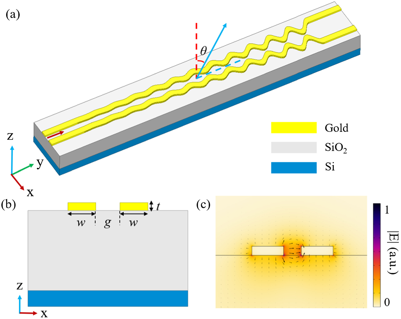
    Fig. 1. (a) 3D schematic view of the proposed low-sidelobe plasmonic antenna. (b) Cross-section view of a uniform plasmonic gap waveguide. (c) E-field distribution of the plasmonic gap mode. The parameters are w=350  nm, g=200  nm, and t=100  nm.
    Schematic views of (a) uniform plasmonic gap waveguide and (b) sinusoidally modulated antenna. (c) Metal absorption loss αc and normalized phase constant versus gap width g0. (d) Average attenuation constant α of the system and leakage factor αr of the antenna as a function of modulation amplitude g1 with g0=600 nm.
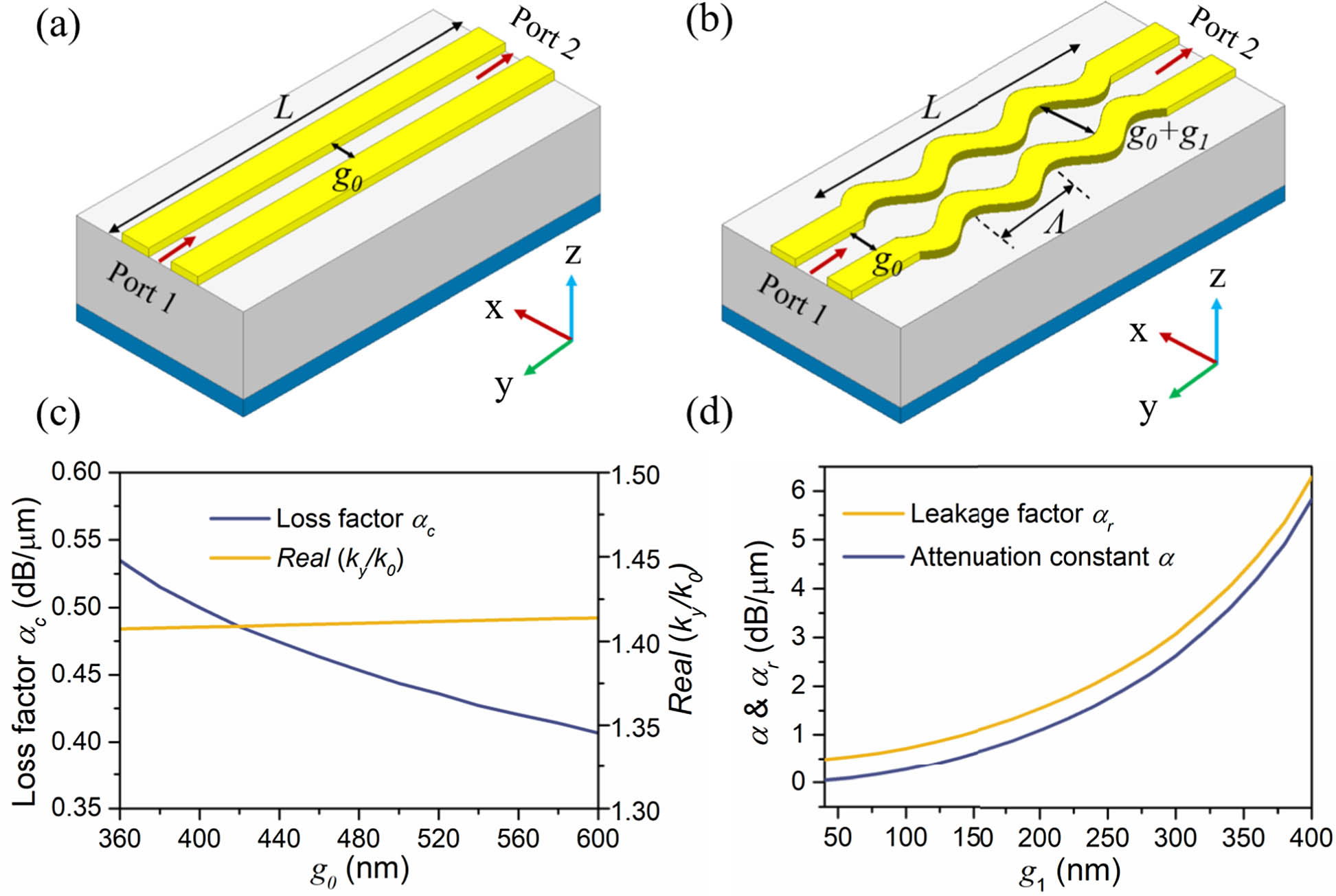
    Fig. 2. Schematic views of (a) uniform plasmonic gap waveguide and (b) sinusoidally modulated antenna. (c) Metal absorption loss αc and normalized phase constant versus gap width g0. (d) Average attenuation constant α of the system and leakage factor αr of the antenna as a function of modulation amplitude g1 with g0=600  nm.
    (a) Target Chebyshev amplitude distribution along antenna radiation aperture. (b) Theoretical modulation amplitudes and leakage factors for the 12 radiation periods. The blue symbols represent the fitting points with a quadratic function formula. (c) Simulated far-field patterns on the yoz plane at 1500, 1550, and 1600 nm. (d) Radiation efficiency and directivity of the proposed LWA within the wavelength range of 1500 to 1600 nm.
    Fig. 3. (a) Target Chebyshev amplitude distribution along antenna radiation aperture. (b) Theoretical modulation amplitudes and leakage factors for the 12 radiation periods. The blue symbols represent the fitting points with a quadratic function formula. (c) Simulated far-field patterns on the yoz plane at 1500, 1550, and 1600 nm. (d) Radiation efficiency and directivity of the proposed LWA within the wavelength range of 1500 to 1600 nm.
    (a) Proposed antenna under the coordinate system. (b) 3D radiation pattern of the designed antenna. (c) Radiation patterns in the xoz and yoz planes. (d) Port reflection coefficient S11 as a function of wavelength.
    Fig. 4. (a) Proposed antenna under the coordinate system. (b) 3D radiation pattern of the designed antenna. (c) Radiation patterns in the xoz and yoz planes. (d) Port reflection coefficient S11 as a function of wavelength.
    SEM image of the (a) referenced structure and (b) fabricated array composed of designed SLL antennas. Measured far-field pattern of the (c) referenced array and (d) proposed design. (e) Measured Fourier-space images of the proposed design at wavelengths of 1527, 1550, and 1570 nm.
    Fig. 5. SEM image of the (a) referenced structure and (b) fabricated array composed of designed SLL antennas. Measured far-field pattern of the (c) referenced array and (d) proposed design. (e) Measured Fourier-space images of the proposed design at wavelengths of 1527, 1550, and 1570 nm.
    (a) Schematic diagram of the operating principle of the proposed leaky-wave antenna. (b) Theoretical normalized radiation pattern in the yoz plane based on the designed Chebyshev amplitude distribution.
    Fig. 6. (a) Schematic diagram of the operating principle of the proposed leaky-wave antenna. (b) Theoretical normalized radiation pattern in the yoz plane based on the designed Chebyshev amplitude distribution.
    (a) Schematic diagram of a uniform linear array. (b) Radiation patterns in the xoz and yoz planes versus the number of antenna elements. (c) Array realized gain as a function of the number of antenna elements in the array.
    Fig. 7. (a) Schematic diagram of a uniform linear array. (b) Radiation patterns in the xoz and yoz planes versus the number of antenna elements. (c) Array realized gain as a function of the number of antenna elements in the array.
    Guang Zhu Zhou, Bao-Jie Chen, Geng-Bo Wu, Shi-Wei Qu, Chi Hou Chan. All-plasmonic optical leaky-wave antenna with a low sidelobe level[J]. Photonics Research, 2023, 11(9): 1500
    Download Citation