• Photonics Research
  • Vol. 11, Issue 6, 1094 (2023)
Yaqing Jin1、2, Ye Yang3、4、5, Huibo Hong1、2, Xiao Xiang1、2, Run'ai Quan1、2, Tao Liu1、2, Ninghua Zhu3、4、6, Ming Li3、4、6、7, Shougang Zhang1、2、8, and Ruifang Dong1、2、*
Author Affiliations
  • 1Key Laboratory of Time and Frequency Primary Standards, National Time Service Center, Chinese Academy of Sciences, Xi’an 710600, China
  • 2School of Astronomy and Space Science, University of Chinese Academy of Sciences, Beijing 100049, China
  • 3State Key Laboratory on Integrated Optoelectronics, Institute of Semiconductors, Chinese Academy of Sciences, Beijing 100083, China
  • 4School of Electronic, Electrical and Communication Engineering, University of Chinese Academy of Sciences, Beijing 100049, China
  • 5The 29th Research Institute of China Electronics Technology Group Corporation, Chengdu 610029, China
  • 6Center of Materials Science and Optoelectronics Engineering, University of Chinese Academy of Sciences, Beijing 100190, China
  • 7e-mail: ml@semi.ac.cn
  • 8e-mail: szhang@ntsc.ac.cn
  • show less
    DOI: 10.1364/PRJ.484142 Cite this Article Set citation alerts
    Yaqing Jin, Ye Yang, Huibo Hong, Xiao Xiang, Run'ai Quan, Tao Liu, Ninghua Zhu, Ming Li, Shougang Zhang, Ruifang Dong. Surpassing the classical limit of the microwave photonic frequency fading effect by quantum microwave photonics[J]. Photonics Research, 2023, 11(6): 1094 Copy Citation Text show less
    Principle diagrams of the QMWP-based nonlocal RF phase shifter and transversal filter. (a) Illustration of nonlocal spectral mapping based on the joint spectrum of frequency anti-correlated photon pairs. Because of the strong frequency anti-correlation, the spectral slicing on the signal photons will be nonlocally mapped onto the idler photons. By adjusting the passband channel of the signal photons, the corresponding passband channel of the idler photons is changed in the opposite direction. (b) Joint temporal distribution profile of the spectrally sliced photon pairs. Due to the strong temporal correlation, the intensity modulation on the idler photons will be nonlocally transferred to the signal photons. (c) Visualized evolution of the temporal correlation distribution and modulation when a dispersive element is applied to the idler photon, which is dispersed in both width and offset. When modulation is applied, the phase shift due to dispersion-induced offset will result. (d) Nonlocal mapping on the idler photons when the optical slicer with multiple passbands is applied. (e) Visualized evolution of the temporal correlation distribution and modulation with the multi-passband slicer on the signal photons and dispersion on the idler photons. (f) Visualized evolution of the temporal correlation distribution and modulation with dispersion applied to the signal photons.
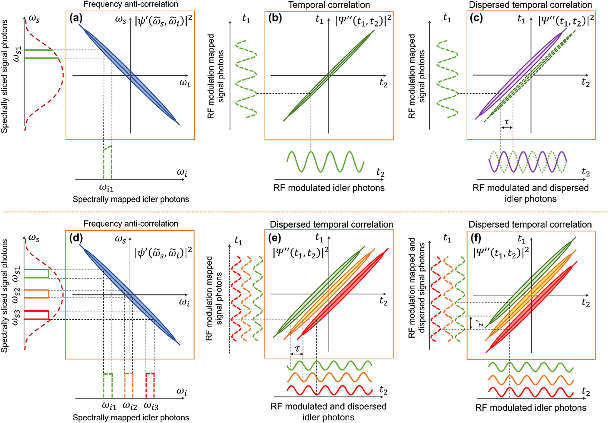
    Fig. 1. Principle diagrams of the QMWP-based nonlocal RF phase shifter and transversal filter. (a) Illustration of nonlocal spectral mapping based on the joint spectrum of frequency anti-correlated photon pairs. Because of the strong frequency anti-correlation, the spectral slicing on the signal photons will be nonlocally mapped onto the idler photons. By adjusting the passband channel of the signal photons, the corresponding passband channel of the idler photons is changed in the opposite direction. (b) Joint temporal distribution profile of the spectrally sliced photon pairs. Due to the strong temporal correlation, the intensity modulation on the idler photons will be nonlocally transferred to the signal photons. (c) Visualized evolution of the temporal correlation distribution and modulation when a dispersive element is applied to the idler photon, which is dispersed in both width and offset. When modulation is applied, the phase shift due to dispersion-induced offset will result. (d) Nonlocal mapping on the idler photons when the optical slicer with multiple passbands is applied. (e) Visualized evolution of the temporal correlation distribution and modulation with the multi-passband slicer on the signal photons and dispersion on the idler photons. (f) Visualized evolution of the temporal correlation distribution and modulation with dispersion applied to the signal photons.
    Experimental setup of the QMWP RF frequency phase shifter and filter. (a) The photon pairs are from the SPDC process. The signal photon is optically sliced by a programmable wave shaper, while the idler photon is modulated and dispersed. Afterwards, the signal and idler photons are detected by a multichannel SNSPD and a TCSPC for recording their time of arrival. By applying the cross-correlation searching algorithm, the paired signal and idler photons are selected out and utilized to reconstruct the photon waveforms. (b) Graphics of the idler photon waveforms when the wavelength channel of the single-passband optical slice is increased, which shows the QMWP functionality of RF phase shifting. (c) Graphics of the idler photon waveforms when the three passbands of the optical slicer take different ratios, which illustrate the QMWP functionality of a three-tap filter with different sidelobe suppression ratios.
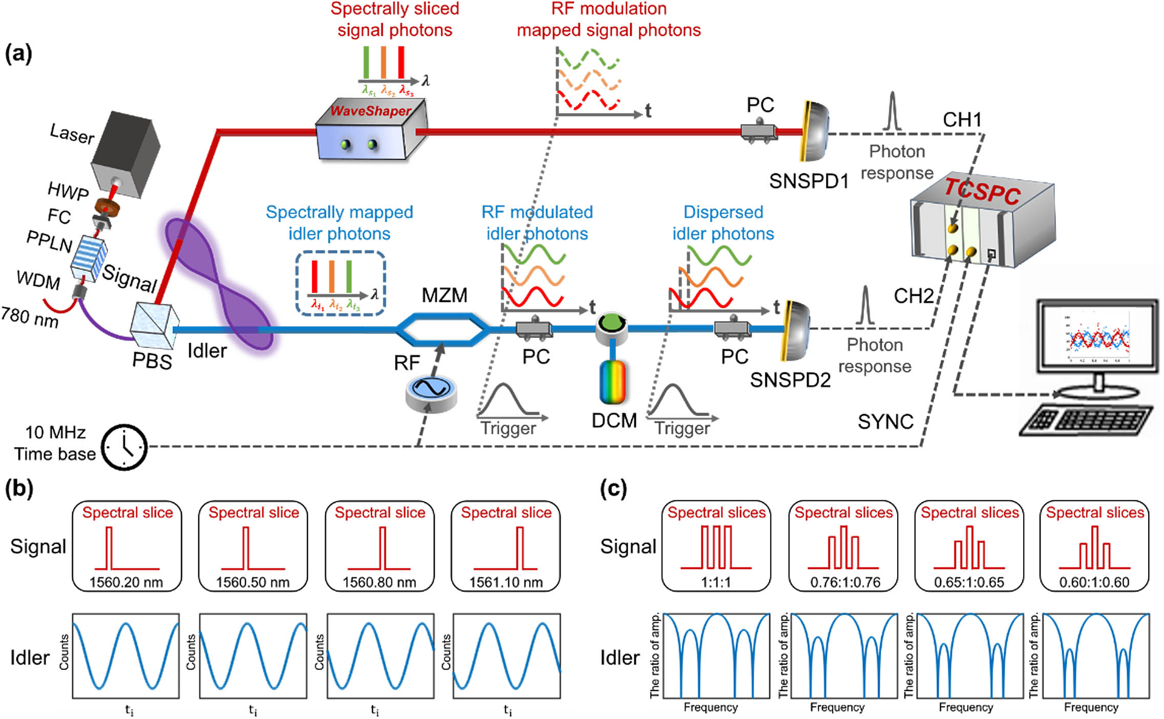
    Fig. 2. Experimental setup of the QMWP RF frequency phase shifter and filter. (a) The photon pairs are from the SPDC process. The signal photon is optically sliced by a programmable wave shaper, while the idler photon is modulated and dispersed. Afterwards, the signal and idler photons are detected by a multichannel SNSPD and a TCSPC for recording their time of arrival. By applying the cross-correlation searching algorithm, the paired signal and idler photons are selected out and utilized to reconstruct the photon waveforms. (b) Graphics of the idler photon waveforms when the wavelength channel of the single-passband optical slice is increased, which shows the QMWP functionality of RF phase shifting. (c) Graphics of the idler photon waveforms when the three passbands of the optical slicer take different ratios, which illustrate the QMWP functionality of a three-tap filter with different sidelobe suppression ratios.
    Results of QMWP-based RF signal phase shifting. (a) Reconstructed temporal waveforms of the signal (red dots) and idler photons (blue squares) when the DCM with a GDD of 165 ps/nm is placed in the idler path and a 3 GHz RF signal is applied. With the adjustment of the central wavelength of the tunable filter, the waveform of the signal photon remains unchanged, while the waveform of the idler photon is left-hand shifted. (b) Reconstructed temporal waveforms of the signal and idler photons when the DCM moves to the signal path while all other settings are maintained. In this case, the waveform of the signal photon is right-hand shifted, while the waveform of the idler photon remains unchanged. (c) Extracted relative phase differences over wavelength between the idler and signal photons’ waveforms in (a) and (b), respectively. The slopes of the linear fits are 3.27±0.07 rad/nm and 3.31±0.03 rad/nm, respectively. According to the direct dependence on the product of ωRF and GDD, the measured GDDs are 173.48±3.71 ps/nm and 175.60±1.59 ps/nm, respectively, which are in good agreement and close to the nominal value of 165 ps/nm GDD. (d), (e) Phase shifting performance when the GDD of the DCM is changed to 330 ps/nm or the RF is set to 5 GHz, respectively. The measured GDDs in (d) and (e) are respectively 346.43±2.23 ps/nm, 349.61±2.86 ps/nm and 172.52±4.77 ps/nm, 175.39±4.24 ps/nm, indicating good agreement with nominal GDD values of the DCMs.
    Fig. 3. Results of QMWP-based RF signal phase shifting. (a) Reconstructed temporal waveforms of the signal (red dots) and idler photons (blue squares) when the DCM with a GDD of 165 ps/nm is placed in the idler path and a 3 GHz RF signal is applied. With the adjustment of the central wavelength of the tunable filter, the waveform of the signal photon remains unchanged, while the waveform of the idler photon is left-hand shifted. (b) Reconstructed temporal waveforms of the signal and idler photons when the DCM moves to the signal path while all other settings are maintained. In this case, the waveform of the signal photon is right-hand shifted, while the waveform of the idler photon remains unchanged. (c) Extracted relative phase differences over wavelength between the idler and signal photons’ waveforms in (a) and (b), respectively. The slopes of the linear fits are 3.27±0.07  rad/nm and 3.31±0.03  rad/nm, respectively. According to the direct dependence on the product of ωRF and GDD, the measured GDDs are 173.48±3.71  ps/nm and 175.60±1.59  ps/nm, respectively, which are in good agreement and close to the nominal value of 165 ps/nm GDD. (d), (e) Phase shifting performance when the GDD of the DCM is changed to 330 ps/nm or the RF is set to 5 GHz, respectively. The measured GDDs in (d) and (e) are respectively 346.43±2.23  ps/nm, 349.61±2.86  ps/nm and 172.52±4.77  ps/nm, 175.39±4.24  ps/nm, indicating good agreement with nominal GDD values of the DCMs.
    Comparison between QMWP and SP-MWP RF filtering. Experimentally acquired three-tap filtering responses in the configurations of QMWP: (a) 330 ps/nm and (b) 495 ps/nm; and SP-MWP: (c) 330 ps/nm and (d) 495 ps/nm. The three-tap RF filtering performance is tested by programming the waveshaper to have three passbands, whose center wavelengths are 1560.95 nm, 1561.75 nm, and 1562.55 nm, and each has an FWHM bandwidth of 0.3 nm. The solid yellow curve depicts the dispersion-induced frequency fading effect without carrier bandwidth contribution, and the solid pink curves in (c) and (d) involve the dispersion-induced frequency fading effect associated with the carrier bandwidth (0.3 nm in our case).
    Fig. 4. Comparison between QMWP and SP-MWP RF filtering. Experimentally acquired three-tap filtering responses in the configurations of QMWP: (a) 330 ps/nm and (b) 495 ps/nm; and SP-MWP: (c) 330 ps/nm and (d) 495 ps/nm. The three-tap RF filtering performance is tested by programming the waveshaper to have three passbands, whose center wavelengths are 1560.95 nm, 1561.75 nm, and 1562.55 nm, and each has an FWHM bandwidth of 0.3 nm. The solid yellow curve depicts the dispersion-induced frequency fading effect without carrier bandwidth contribution, and the solid pink curves in (c) and (d) involve the dispersion-induced frequency fading effect associated with the carrier bandwidth (0.3 nm in our case).
    Reconfigurability of the three-tap QMWP RF filter. The three passbands of the waveshaper are maintained at center wavelengths of 1560.95 nm, 1561.75 nm, and 1562.55 nm. Reconfigurable sidelobe suppression of the three-tap RF filter is investigated via the filtering responses with a GDD of 330 ps/nm, while the three passbands’ photon flux ratios are taken as (a) 0.76:1:0.76, (b) 0.65:1:0.65, and (c) 0.60:1:0.60, which correspond to sidelobe suppression ratios of (a) 6.48 dB, (b) 8.80 dB, and (c) 10.66 dB, respectively. (d) Comparison between the measured MSLR of QMWP nonlocal filtering and the simulation of classic MWP filtering.
    Fig. 5. Reconfigurability of the three-tap QMWP RF filter. The three passbands of the waveshaper are maintained at center wavelengths of 1560.95 nm, 1561.75 nm, and 1562.55 nm. Reconfigurable sidelobe suppression of the three-tap RF filter is investigated via the filtering responses with a GDD of 330 ps/nm, while the three passbands’ photon flux ratios are taken as (a) 0.76:1:0.76, (b) 0.65:1:0.65, and (c) 0.60:1:0.60, which correspond to sidelobe suppression ratios of (a) 6.48 dB, (b) 8.80 dB, and (c) 10.66 dB, respectively. (d) Comparison between the measured MSLR of QMWP nonlocal filtering and the simulation of classic MWP filtering.
    Two-dimensional parallel QMWP RF filtering demonstration. In the experimental setup, the DCM of −330 ps/nm is placed in the signal path, while the DCM of 165 ps/nm is placed in the idler path: (a) RF filtering result extracted from the signal photon waveform and (b) RF filtering result extracted from the idler photon waveform.
    Fig. 6. Two-dimensional parallel QMWP RF filtering demonstration. In the experimental setup, the DCM of 330  ps/nm is placed in the signal path, while the DCM of 165 ps/nm is placed in the idler path: (a) RF filtering result extracted from the signal photon waveform and (b) RF filtering result extracted from the idler photon waveform.
    Coincidence histograms between the signal and idler photons for post-selection. (a) Coincidence result for the optical filter with a single passband; (b), (c) coincidence results for the optical filter with three passbands when the photon flux ratio of the passband is taken as (b) 1:1:1 and (c) 0.65 1 0.65.
    Fig. 7. Coincidence histograms between the signal and idler photons for post-selection. (a) Coincidence result for the optical filter with a single passband; (b), (c) coincidence results for the optical filter with three passbands when the photon flux ratio of the passband is taken as (b) 1:1:1 and (c) 0.65 1 0.65.
    Reconstructed waveforms of the QMWP-based three-tap RF filter. (a) Waveform at filter’s passband (fRF=3.5 GHz, GDD=330 ps/nm); (b) waveform at filter’s stopband fRF=4.76 GHz, GDD=330 ps/nm.
    Fig. 8. Reconstructed waveforms of the QMWP-based three-tap RF filter. (a) Waveform at filter’s passband (fRF=3.5  GHz, GDD=330  ps/nm); (b) waveform at filter’s stopband fRF=4.76  GHz, GDD=330  ps/nm.
    Tunability of the three-tap QMWP RF filter. Filtering responses with the GDD of the DCM in the idler path at values of (a) 165 ps/nm, (b) 330 ps/nm, and (c) 495 ps/nm, which result in FSRs of (a) 7 GHz, (b) 3.5 GHz, and (c) 2.35 GHz, respectively.
    Fig. 9. Tunability of the three-tap QMWP RF filter. Filtering responses with the GDD of the DCM in the idler path at values of (a) 165 ps/nm, (b) 330 ps/nm, and (c) 495 ps/nm, which result in FSRs of (a) 7 GHz, (b) 3.5 GHz, and (c) 2.35 GHz, respectively.
    Experimental filtering response when the DCM with the GDD of 330 ps/nm is placed in the signal path.
    Fig. 10. Experimental filtering response when the DCM with the GDD of 330 ps/nm is placed in the signal path.
    Yaqing Jin, Ye Yang, Huibo Hong, Xiao Xiang, Run'ai Quan, Tao Liu, Ninghua Zhu, Ming Li, Shougang Zhang, Ruifang Dong. Surpassing the classical limit of the microwave photonic frequency fading effect by quantum microwave photonics[J]. Photonics Research, 2023, 11(6): 1094
    Download Citation