
Bo Fu, Jin Li, Zhang Cao, Daniel Popa. Bound states of solitons in a harmonic graphene-mode-locked fiber laser[J]. Photonics Research, 2019, 7(2): 116
- Photonics Research
- Vol. 7, Issue 2, 116 (2019)
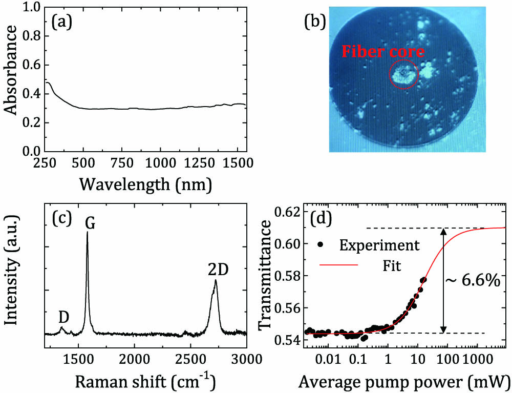
Fig. 1. (a) Linear absorption of the graphene solution (alcohol contribution subtracted); (b) GSA film optically deposited on fiber tip; (c) Raman spectrum of GSA film on fiber tip; (d) nonlinear transmittance at the laser operating wavelength.
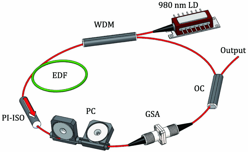
Fig. 2. All-fiber laser schematic. LD, laser diode; WDM, wavelength-division multiplexer; EDF, Er-doped fiber; PI-ISO, polarization-insensitive isolator; PC, polarization controller; GSA, graphene saturable absorber; OC, optical coupler.
Fig. 3. Fundamental mode-locking experimental results. (a) Optical spectrum; (b) temporal waveform; (c) pulse profile; (d) RF spectrum with 10 Hz resolution (inset, 1000 MHz span).
Fig. 4. BS experimental results. (a), (b), and (c) BS spectral modulations as functions of intracavity polarization, with a stable CW-free spectrum shown in (c) (inset, spectral magnification around the central wavelength, 1558 nm); (d) autocorrelation trace of the pulses (inset, pulse profile). The pulse separation Δ τ 1 / Δ τ
Fig. 5. HML experimental results. (a) Optical spectrum (inset, pulse profile); (b) temporal waveform; (c) RF spectrum with 20 kHz resolution (inset, 1500 MHz span); (d) output power and harmonic order as functions of pump power.

Set citation alerts for the article
Please enter your email address
© Copyright 2018-2021 | Chinese Laser Press. All Rights Reserved 沪ICP备15018463号-20