• Photonics Research
  • Vol. 12, Issue 4, 663 (2024)
Baoqi Shi1、2、†, Yi-Han Luo2、3、†, Wei Sun2, Yue Hu2、3, Jinbao Long2, Xue Bai2, Anting Wang1、5, and Junqiu Liu2、4、*
Author Affiliations
  • 1Department of Optics and Optical Engineering, University of Science and Technology of China, Hefei 230026, China
  • 2International Quantum Academy, Shenzhen 518048, China
  • 3Shenzhen Institute for Quantum Science and Engineering, Southern University of Science and Technology, Shenzhen 518055, China
  • 4Hefei National Laboratory, University of Science and Technology of China, Hefei 230088, China
  • 5e-mail: atwang@ustc.edu.cn
  • show less
    DOI: 10.1364/PRJ.510795 Cite this Article Set citation alerts
    Baoqi Shi, Yi-Han Luo, Wei Sun, Yue Hu, Jinbao Long, Xue Bai, Anting Wang, Junqiu Liu. Frequency-comb-linearized, widely tunable lasers for coherent ranging[J]. Photonics Research, 2024, 12(4): 663 Copy Citation Text show less
    Applications and principle of widely tunable lasers. (a) Applications requiring linearly chirping lasers. OCT, optical coherence tomography; OFDR, optical frequency-domain reflectometry; LiDAR, light detection and ranging. (b) Principle of laser chirp linearization. An ideal laser chirps at a constant rate. However, in reality, the actual chirp rate varies. By beating the laser with its delayed part, the chirp nonlinearity in the optical domain is revealed in the radio frequency (RF) domain.
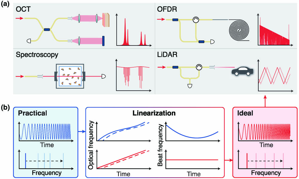
    Fig. 1. Applications and principle of widely tunable lasers. (a) Applications requiring linearly chirping lasers. OCT, optical coherence tomography; OFDR, optical frequency-domain reflectometry; LiDAR, light detection and ranging. (b) Principle of laser chirp linearization. An ideal laser chirps at a constant rate. However, in reality, the actual chirp rate varies. By beating the laser with its delayed part, the chirp nonlinearity in the optical domain is revealed in the radio frequency (RF) domain.
    Schematic and experimental setup of laser chirp characterization. (a) Experimental setup. BPF, band-pass filter; PC, polarization controller; BPD, balanced photodetector; LPF, low-pass filter; OSC, oscilloscope. (b) Illustration of the laser frequency beating with the OFC during laser chirping at a rate of α. The time traces of the two beat frequencies β1 and β2 (β2>β1) are shown. (c) Upper panel shows the instantaneous frequency of the tunable laser in the ideal (red) and actual (blue) cases. Lower panel shows the corresponding instantaneous chirp rate α. (d) Flowcharts of the algorithm based on finite impulse response (FIR) band-pass filters (BPFs), to extract the instantaneous laser frequency as well as the chirp rate. The dashed lines mark the time where the laser frequency scans across a comb line. (e) The FIR filter’s center frequency fFIR is digitally set, and the instantaneous laser frequency is calculated over 1 MHz intervals.
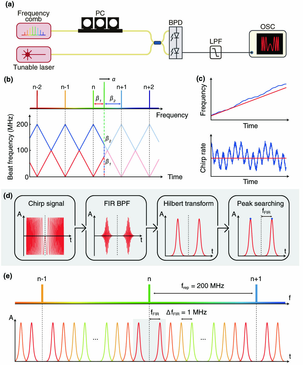
    Fig. 2. Schematic and experimental setup of laser chirp characterization. (a) Experimental setup. BPF, band-pass filter; PC, polarization controller; BPD, balanced photodetector; LPF, low-pass filter; OSC, oscilloscope. (b) Illustration of the laser frequency beating with the OFC during laser chirping at a rate of α. The time traces of the two beat frequencies β1 and β2 (β2>β1) are shown. (c) Upper panel shows the instantaneous frequency of the tunable laser in the ideal (red) and actual (blue) cases. Lower panel shows the corresponding instantaneous chirp rate α. (d) Flowcharts of the algorithm based on finite impulse response (FIR) band-pass filters (BPFs), to extract the instantaneous laser frequency as well as the chirp rate. The dashed lines mark the time where the laser frequency scans across a comb line. (e) The FIR filter’s center frequency fFIR is digitally set, and the instantaneous laser frequency is calculated over 1 MHz intervals.
    Characterization of Toptica CTL laser’s chirp dynamics. (a) Normalized chirp rate α(λ)/αset with different set values αset over 0.2 nm wavelength range. (b) Frequency spectra of the normalized chirp rate α(t)/αset. The frequency values of prominent peaks are marked. (c) Normalized chirp rate α(λ)/αset with different set values αset over 10 nm wavelength range.
    Fig. 3. Characterization of Toptica CTL laser’s chirp dynamics. (a) Normalized chirp rate α(λ)/αset with different set values αset over 0.2 nm wavelength range. (b) Frequency spectra of the normalized chirp rate α(t)/αset. The frequency values of prominent peaks are marked. (c) Normalized chirp rate α(λ)/αset with different set values αset over 10 nm wavelength range.
    Coherent LiDAR experiment. (a) Maps of measured relative distance of an engraved surface with pre-linearization and without linearization. The sample’s tilt angle of 11.6° is measured and subtracted. (b) Space spectra of the ranging profiles obtained with pre-linearization and without linearization. Fast Fourier transform is applied on the ranging profile of each case to retrieve the spectrum. The peaks correspond to the distance d=4 m of the surface to the laser.
    Fig. 4. Coherent LiDAR experiment. (a) Maps of measured relative distance of an engraved surface with pre-linearization and without linearization. The sample’s tilt angle of 11.6° is measured and subtracted. (b) Space spectra of the ranging profiles obtained with pre-linearization and without linearization. Fast Fourier transform is applied on the ranging profile of each case to retrieve the spectrum. The peaks correspond to the distance d=4  m of the surface to the laser.
    Comparison of three Toptica lasers’ chirp dynamics in the wide tuning mode. (a) Normalized chirp rate α(λ)/αset of the three Toptica lasers with different set values αset over 0.2 nm wavelength range. (b) Frequency spectra of the chirp rate α(t)/αset.
    Fig. 5. Comparison of three Toptica lasers’ chirp dynamics in the wide tuning mode. (a) Normalized chirp rate α(λ)/αset of the three Toptica lasers with different set values αset over 0.2 nm wavelength range. (b) Frequency spectra of the chirp rate α(t)/αset.
    Characterization of chirp dynamics of a Santec laser in the wide tuning mode. (a) Normalized chirp rate α(λ)/αset with different set values αset over 0.2 nm wavelength range. (b) Frequency spectra of the chirp rate α(t)/αset. (c) Normalized chirp rate α(λ)/αset with αset=100 nm/s over 10 nm wavelength range.
    Fig. 6. Characterization of chirp dynamics of a Santec laser in the wide tuning mode. (a) Normalized chirp rate α(λ)/αset with different set values αset over 0.2 nm wavelength range. (b) Frequency spectra of the chirp rate α(t)/αset. (c) Normalized chirp rate α(λ)/αset with αset=100  nm/s over 10 nm wavelength range.
    Comparison of four Santec lasers’ chirp dynamics in the wide tuning mode. (a) Normalized chirp rate α(λ)/αset of the four Santec lasers with αset=5 nm/s over 0.2 nm wavelength range. (b) Frequency spectra of the chirp rate α(t)/αset.
    Fig. 7. Comparison of four Santec lasers’ chirp dynamics in the wide tuning mode. (a) Normalized chirp rate α(λ)/αset of the four Santec lasers with αset=5  nm/s over 0.2 nm wavelength range. (b) Frequency spectra of the chirp rate α(t)/αset.
    Characterization of chirp dynamics of a New Focus laser in the wide tuning mode. (a) Normalized chirp rate α(λ)/αset with different set values αset over 0.2 nm wavelength range. (b) Frequency spectra of the chirp rate α(t)/αset. (c) Normalized chirp rate α(λ)/αset with different set values αset over 10 nm wavelength range.
    Fig. 8. Characterization of chirp dynamics of a New Focus laser in the wide tuning mode. (a) Normalized chirp rate α(λ)/αset with different set values αset over 0.2 nm wavelength range. (b) Frequency spectra of the chirp rate α(t)/αset. (c) Normalized chirp rate α(λ)/αset with different set values αset over 10 nm wavelength range.
    Characterization of chirp dynamics of an EXFO laser in the wide tuning mode. (a) Normalized chirp rate α(λ)/αset with different set values αset over 0.2 nm wavelength range. (b) Frequency spectra of the chirp rate α(t)/αset.
    Fig. 9. Characterization of chirp dynamics of an EXFO laser in the wide tuning mode. (a) Normalized chirp rate α(λ)/αset with different set values αset over 0.2 nm wavelength range. (b) Frequency spectra of the chirp rate α(t)/αset.
    Characterization of chirp dynamics of an NKT laser in the fine tuning mode. (a) Normalized chirp rate α(fl)/αset with different set values fmod over 6 GHz frequency range. The piezo of the laser is driven by a triangular (blue) or a sinusoidal (red) signal. (b) Frequency spectra of the chirp rate α(t)/αset.
    Fig. 10. Characterization of chirp dynamics of an NKT laser in the fine tuning mode. (a) Normalized chirp rate α(fl)/αset with different set values fmod over 6 GHz frequency range. The piezo of the laser is driven by a triangular (blue) or a sinusoidal (red) signal. (b) Frequency spectra of the chirp rate α(t)/αset.
    Characterization of chirp dynamics of two NKT lasers in the fine tuning mode. (a) Normalized chirp rate α(fl)/αset with fmod=10 Hz over 6 GHz frequency range. The piezo of the laser is driven by a triangular (blue) or a sinusoidal (red) signal. (b) Frequency spectra of the chirp rate α(t)/αset.
    Fig. 11. Characterization of chirp dynamics of two NKT lasers in the fine tuning mode. (a) Normalized chirp rate α(fl)/αset with fmod=10  Hz over 6 GHz frequency range. The piezo of the laser is driven by a triangular (blue) or a sinusoidal (red) signal. (b) Frequency spectra of the chirp rate α(t)/αset.
    Characterization of chirp dynamics of a Santec laser in the fine tuning mode. (a) Normalized chirp rate α(fl)/αset with different set values fmod over 9 GHz frequency range. The piezo of the laser is driven by a triangular (blue) or a sinusoidal (red) signal. (b) Frequency spectra of the chirp rate α(t)/αset.
    Fig. 12. Characterization of chirp dynamics of a Santec laser in the fine tuning mode. (a) Normalized chirp rate α(fl)/αset with different set values fmod over 9 GHz frequency range. The piezo of the laser is driven by a triangular (blue) or a sinusoidal (red) signal. (b) Frequency spectra of the chirp rate α(t)/αset.
    Characterization of chirp dynamics of four Santec lasers in the fine tuning mode. (a) Normalized chirp rate α(fl)/αset with fmod=2 Hz over 9 GHz frequency range. The piezo of the laser is driven by a triangular (blue) or a sinusoidal (red) signal. (b) Frequency spectra of the chirp rate α(t)/αset.
    Fig. 13. Characterization of chirp dynamics of four Santec lasers in the fine tuning mode. (a) Normalized chirp rate α(fl)/αset with fmod=2  Hz over 9 GHz frequency range. The piezo of the laser is driven by a triangular (blue) or a sinusoidal (red) signal. (b) Frequency spectra of the chirp rate α(t)/αset.
    Characterization of chirp dynamics of a Toptica laser in the fine tuning mode. (a) Normalized chirp rate α(fl)/αset with different set values fmod over 9 GHz frequency range. The piezo of the laser is driven by a triangular (blue) or a sinusoidal (red) signal. (b) Frequency spectra of the chirp rate α(t)/αset.
    Fig. 14. Characterization of chirp dynamics of a Toptica laser in the fine tuning mode. (a) Normalized chirp rate α(fl)/αset with different set values fmod over 9 GHz frequency range. The piezo of the laser is driven by a triangular (blue) or a sinusoidal (red) signal. (b) Frequency spectra of the chirp rate α(t)/αset.
    (a) Different drive signals. (b) Fourier transform of different drive signals.
    Fig. 15. (a) Different drive signals. (b) Fourier transform of different drive signals.
    Characterization of chirp dynamics of three Toptica lasers in the fine tuning mode. (a) Normalized chirp rate α(fl)/αset with fmod=50 Hz over 9 GHz frequency range. The piezo of the laser is driven by a triangular (blue) or a sinusoidal (red) signal. (b) Frequency spectra of the chirp rate α(t)/αset.
    Fig. 16. Characterization of chirp dynamics of three Toptica lasers in the fine tuning mode. (a) Normalized chirp rate α(fl)/αset with fmod=50  Hz over 9 GHz frequency range. The piezo of the laser is driven by a triangular (blue) or a sinusoidal (red) signal. (b) Frequency spectra of the chirp rate α(t)/αset.
    Characterization of chirp dynamics of a New Focus laser in the fine tuning mode. (a) Normalized chirp rate α(fl)/αset with different set values fmod over 9 GHz frequency range. The piezo of the laser is driven by a triangular (blue) or a sinusoidal (red) signal. (b) Frequency spectra of the chirp rate α(t)/αset.
    Fig. 17. Characterization of chirp dynamics of a New Focus laser in the fine tuning mode. (a) Normalized chirp rate α(fl)/αset with different set values fmod over 9 GHz frequency range. The piezo of the laser is driven by a triangular (blue) or a sinusoidal (red) signal. (b) Frequency spectra of the chirp rate α(t)/αset.
    Laser characterization for LiDAR demonstration. (a) Normalized chirp rate α(fl)/αset with different set values fmod over 24 GHz frequency range. The piezo of the laser is driven by a triangular (blue) or a sinusoidal (red) signal. (b) Frequency spectra of the chirp rate α(t)/αset. (c) Upper panel shows the chirp rate curve α(t) (blue) and pre-linearization curve αc(t) (red). Lower panel shows the linearized chirp rate curve α(t)/αc(t). (d) Frequency spectrum of the linearized chirp rate in the lower panel of panel (c). The dotted and dashed line shows its averaged amplitude below 100 kHz. The dashed line shows the averaged amplitude of normalized chirp rate α(t)/αset(t)’s frequency spectrum below 100 kHz.
    Fig. 18. Laser characterization for LiDAR demonstration. (a) Normalized chirp rate α(fl)/αset with different set values fmod over 24 GHz frequency range. The piezo of the laser is driven by a triangular (blue) or a sinusoidal (red) signal. (b) Frequency spectra of the chirp rate α(t)/αset. (c) Upper panel shows the chirp rate curve α(t) (blue) and pre-linearization curve αc(t) (red). Lower panel shows the linearized chirp rate curve α(t)/αc(t). (d) Frequency spectrum of the linearized chirp rate in the lower panel of panel (c). The dotted and dashed line shows its averaged amplitude below 100 kHz. The dashed line shows the averaged amplitude of normalized chirp rate α(t)/αset(t)’s frequency spectrum below 100 kHz.
    Setup for LiDAR demonstration and precision test. (a) Experimental setup. BPD, balanced photodetector; OSC, oscilloscope. (b) Histogram of deviation of ranging measurement. The long-term stability of pre-linearization is verified by a precision test. A mirror is fixed at a distance of 53.361 mm and measured 1128 times every 3 s. The standard deviation of the measured distance is 11 μm.
    Fig. 19. Setup for LiDAR demonstration and precision test. (a) Experimental setup. BPD, balanced photodetector; OSC, oscilloscope. (b) Histogram of deviation of ranging measurement. The long-term stability of pre-linearization is verified by a precision test. A mirror is fixed at a distance of 53.361 mm and measured 1128 times every 3 s. The standard deviation of the measured distance is 11 μm.
    Laser BrandModelTuning ModeOptimal αsetfmodChirp RangeRMSEδL
    TopticaCTL 1550Wide, single2 nm/s (0.24 THz/s)10 nm (1.2 THz)7.5% (1.1%)0.2% (0.0%)
    SantecTSL-570-AWide, single100 nm/s (12 THz/s)10 nm (1.2 THz)6.8% (1.6%)0.4% (0.2%)
    New FocusTLB-6700Wide, single2 nm/s (0.24 THz/s)10 nm (1.2 THz)12.9% (1.9%)0.3% (0.2%)
    EXFOT500SWide, single100 nm/s (12 THz/s)10 nm (1.2 THz)4.8%0.2%
    TopticaCTL 1550Fine, triangular1.6 nm/s (200 GHz/s)10 Hz80 pm (10 GHz)7.8% (1.3%)0.8% (0.0%)
    SantecTSL-570-AFine, triangular1.6 nm/s (200 GHz/s)10 Hz80 pm (10 GHz)14.1% (0.6%)1.8% (0.1%)
    New FocusTLB-6700Fine, triangular8 nm/s (1 THz/s)50 Hz80 pm (10 GHz)17.9% (12.1%)0.4% (0.1%)
    NKTE15Fine, triangular256 pm/s (32 GHz/s)2 Hz64 pm (8 GHz)5.6% (1.9%)0.5% (0.3%)
    TopticaCTL 1550Fine, sinusoidal8 nm/s (1 THz/s)50 Hz80 pm (10 GHz)7.4% (0.2%)
    SantecTSL-570-AFine, sinusoidal1.6 nm/s (200 GHz/s)10 Hz80 pm (10 GHz)16.4% (0.5%)
    New FocusTLB-6700Fine, sinusoidal16 nm/s (2 THz/s)100 Hz80 pm (10 GHz)8.4% (4.2%)
    NKTE15Fine, sinusoidal256 pm/s (32 GHz/s)2 Hz64 pm (8 GHz)6.5% (1.0%)
    Table 1. Comparison of Laser Chirp Dynamics of Different Lasers with Different Conditions
    Baoqi Shi, Yi-Han Luo, Wei Sun, Yue Hu, Jinbao Long, Xue Bai, Anting Wang, Junqiu Liu. Frequency-comb-linearized, widely tunable lasers for coherent ranging[J]. Photonics Research, 2024, 12(4): 663
    Download Citation