• Photonics Research
  • Vol. 12, Issue 3, 423 (2024)
Shijie Sun, Qidong Yu, Yuanhua Che, Tianhang Lian, Yuhang Xie, Daming Zhang, and Xibin Wang*
Author Affiliations
  • State Key Laboratory of Integrated Optoelectronics, College of Electronic Science and Engineering, Jilin University, Changchun 130012, China
  • show less
    DOI: 10.1364/PRJ.509773 Cite this Article Set citation alerts
    Shijie Sun, Qidong Yu, Yuanhua Che, Tianhang Lian, Yuhang Xie, Daming Zhang, Xibin Wang. Mode-insensitive and mode-selective optical switch based on asymmetric Y-junctions and MMI couplers[J]. Photonics Research, 2024, 12(3): 423 Copy Citation Text show less
    (a) Schematic diagram of the proposed device. Enlarged view for (b) the asymmetric Y-junction and (c) the MMI coupler. (d) Cross-section for the modulation region.
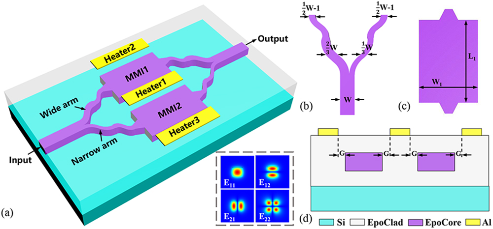
    Fig. 1. (a) Schematic diagram of the proposed device. Enlarged view for (b) the asymmetric Y-junction and (c) the MMI coupler. (d) Cross-section for the modulation region.
    (a) Thermal field distribution of the device when Heater-1 is turned on. (b) Simulated transmission of the E11, E12, E21, and E22 modes as a function of ΔT1. (c) Simulated transmission spectra of the E11, E12, E21, and E22 modes as a function of the wavelength. (d) Simulated propagation results at 1550 nm wavelength for each mode individually.
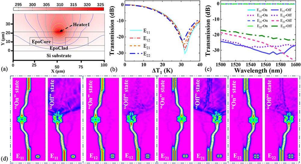
    Fig. 2. (a) Thermal field distribution of the device when Heater-1 is turned on. (b) Simulated transmission of the E11, E12, E21, and E22 modes as a function of ΔT1. (c) Simulated transmission spectra of the E11, E12, E21, and E22 modes as a function of the wavelength. (d) Simulated propagation results at 1550 nm wavelength for each mode individually.
    (a) Thermal field distribution of the device when Heater-2 is on. (b) Simulated transmission of the E11, E12, E21, and E22 modes as a function of ΔT2. (c) Thermal field distribution of the device when Heater-3 is on. (b) Simulated transmission of the E11, E12, E21, and E22 modes as a function of ΔT3.
    Fig. 3. (a) Thermal field distribution of the device when Heater-2 is on. (b) Simulated transmission of the E11, E12, E21, and E22 modes as a function of ΔT2. (c) Thermal field distribution of the device when Heater-3 is on. (b) Simulated transmission of the E11, E12, E21, and E22 modes as a function of ΔT3.
    (a) Steps in the fabrication of the proposed MWOS with polymer materials. The top-view microscope images of (b) the asymmetric Y-junction and (c) the MMI couplers. Microscope images of (d) the electrode heater and (e) an end face of the fabricated device.
    Fig. 4. (a) Steps in the fabrication of the proposed MWOS with polymer materials. The top-view microscope images of (b) the asymmetric Y-junction and (c) the MMI couplers. Microscope images of (d) the electrode heater and (e) an end face of the fabricated device.
    (a) Measured transmission of the E11, E12, E21, and E22 modes as a function of P1. (b) Measured transmission spectra of the E11, E12, E21, and E22 modes as a function of the wavelength. (c) Output near-field photos with different P1 when E11, E12, E21, or E22 mode was launched into the device at the 1550 nm wavelength.
    Fig. 5. (a) Measured transmission of the E11, E12, E21, and E22 modes as a function of P1. (b) Measured transmission spectra of the E11, E12, E21, and E22 modes as a function of the wavelength. (c) Output near-field photos with different P1 when E11, E12, E21, or E22 mode was launched into the device at the 1550 nm wavelength.
    (a) Measured transmission of the E11, E12, E21, and E22 modes as a function of P2. (b) Output near-field photos with different P2 when the E11, E12, E21, or E22 modes were launched into the device at the 1550 nm wavelength. (c) Measured transmission of the E11, E12, E21 and E22 modes as a function of P3. (d) Output near-field photos with different P3 when E11, E12, E21, or E22 mode was launched into the device at the 1550 nm wavelength.
    Fig. 6. (a) Measured transmission of the E11, E12, E21, and E22 modes as a function of P2. (b) Output near-field photos with different P2 when the E11, E12, E21, or E22 modes were launched into the device at the 1550 nm wavelength. (c) Measured transmission of the E11, E12, E21 and E22 modes as a function of P3. (d) Output near-field photos with different P3 when E11, E12, E21, or E22 mode was launched into the device at the 1550 nm wavelength.
    Measured dynamic switching of the proposed MWOS when the (a) E11, (b) E12, (c) E21, and (d) E22 modes were launched into the device.
    Fig. 7. Measured dynamic switching of the proposed MWOS when the (a) E11, (b) E12, (c) E21, and (d) E22 modes were launched into the device.
    Schematic structure of an eight-mode multifunctional switch.
    Fig. 8. Schematic structure of an eight-mode multifunctional switch.
    Shijie Sun, Qidong Yu, Yuanhua Che, Tianhang Lian, Yuhang Xie, Daming Zhang, Xibin Wang. Mode-insensitive and mode-selective optical switch based on asymmetric Y-junctions and MMI couplers[J]. Photonics Research, 2024, 12(3): 423
    Download Citation