• Advanced Photonics
  • Vol. 5, Issue 5, 056003 (2023)
Hongya Wang1、2, Jianzhou Ai1、2, Zelin Ma3, Siddharth Ramachandran3, and Jian Wang1、2、*
Author Affiliations
  • 1Huazhong University of Science and Technology, Wuhan National Laboratory for Optoelectronics and School of Optical and Electronic Information, Wuhan, China
  • 2Optics Valley Laboratory, Wuhan, China
  • 3Boston University, Boston, Massachusetts, United States
  • show less
    DOI: 10.1117/1.AP.5.5.056003 Cite this Article Set citation alerts
    Hongya Wang, Jianzhou Ai, Zelin Ma, Siddharth Ramachandran, Jian Wang. Finding the superior mode basis for mode-division multiplexing: a comparison of spatial modes in air-core fiber[J]. Advanced Photonics, 2023, 5(5): 056003 Copy Citation Text show less
    Concept and principle of a comparison among different spatial mode bases (LP, LP-OAM, vector, and CP-OAM) in ACF. (a) Intrinsic mode walk-off for LP/LP-OAM modes and no mode walk-off for vector/CP-OAM modes. (b) Data-carrying MDM transmission using spatial modes with large Δneff (negligible cross talk and MIMO-free) under fiber perturbations. (c) Data-carrying MDM transmisison using degenerate vector modes (strong cross talk) or degenerate CP-OAM modes (negligible cross talk and MIMO-free) under fiber perturbations.
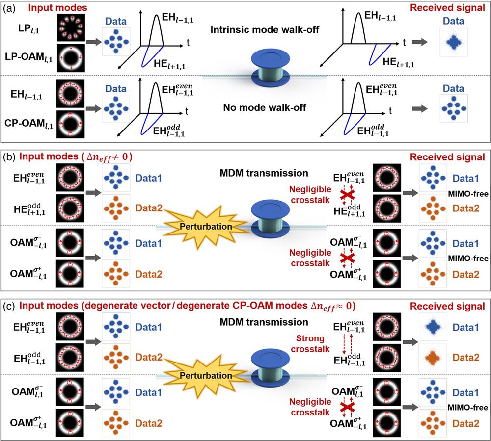
    Fig. 1. Concept and principle of a comparison among different spatial mode bases (LP, LP-OAM, vector, and CP-OAM) in ACF. (a) Intrinsic mode walk-off for LP/LP-OAM modes and no mode walk-off for vector/CP-OAM modes. (b) Data-carrying MDM transmission using spatial modes with large Δneff (negligible cross talk and MIMO-free) under fiber perturbations. (c) Data-carrying MDM transmisison using degenerate vector modes (strong cross talk) or degenerate CP-OAM modes (negligible cross talk and MIMO-free) under fiber perturbations.
    Characterization of the ACF and experimental setup for spatial modes transmission in ACF. (a) Measured refractive index profile of the ACF. (b) The Δneff between adjacent OAM modes within each OAM mode group for |l|=5,6,7 in the ACF. (c) Experimental setup for spatial modes (LP, LP-OAM, vector, and CP-OAM) transmission in ACF. Right inset, optical microscope image of the ACF facet. Bottom insets, phase patterns loaded onto SLM to generate LP7,1, OAM−7,1, OAM7,1, OAM−6,1, and OAM6,1 modes. SLM, spatial light modulator; OL, objective lens; BS, beam splitter; PC, polarization controller.
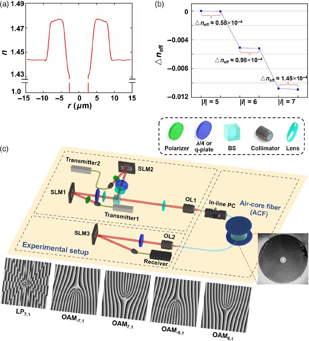
    Fig. 2. Characterization of the ACF and experimental setup for spatial modes transmission in ACF. (a) Measured refractive index profile of the ACF. (b) The Δneff between adjacent OAM modes within each OAM mode group for |l|=5,6,7 in the ACF. (c) Experimental setup for spatial modes (LP, LP-OAM, vector, and CP-OAM) transmission in ACF. Right inset, optical microscope image of the ACF facet. Bottom insets, phase patterns loaded onto SLM to generate LP7,1, OAM7,1, OAM7,1, OAM6,1, and OAM6,1 modes. SLM, spatial light modulator; OL, objective lens; BS, beam splitter; PC, polarization controller.
    Basic properties of spatial modes transmission in ACF. (a)–(d) Measured intensity profiles of different spatial modes after 1-km ACF transmission. (a) LP7,1 mode; (b) LP-OAM7,1 mode; (c) CP-OAM modes (top, doughnut-shaped intensity profiles; bottom, interference patterns with a reference Gaussian beam); (d) vector mode (EH6,1) and its intensity profiles after passing through a rotating linear polarizer. (e)–(j) Pulse response of different spatial modes after 1-km ACF transmission. (e) LP7,1 without perturbation; (f) LP-OAM7,1 without perturbation; (g) EH6,1 without perturbation; (h) CP-OAM7,1 without perturbation; (i) EH6,1 with perturbation; (j) CP-OAM7,1 with perturbation. w/: with. w/o: without. (k), (l) Power evolution of degenerate vector modes and degenerate CP-OAM modes under out-of-plane fiber movements. (k) Launching mode: EH6,1even; (l) launching mode: OAM−7,1σ+.
    Fig. 3. Basic properties of spatial modes transmission in ACF. (a)–(d) Measured intensity profiles of different spatial modes after 1-km ACF transmission. (a) LP7,1 mode; (b) LP-OAM7,1 mode; (c) CP-OAM modes (top, doughnut-shaped intensity profiles; bottom, interference patterns with a reference Gaussian beam); (d) vector mode (EH6,1) and its intensity profiles after passing through a rotating linear polarizer. (e)–(j) Pulse response of different spatial modes after 1-km ACF transmission. (e) LP7,1 without perturbation; (f) LP-OAM7,1 without perturbation; (g) EH6,1 without perturbation; (h) CP-OAM7,1 without perturbation; (i) EH6,1 with perturbation; (j) CP-OAM7,1 with perturbation. w/: with. w/o: without. (k), (l) Power evolution of degenerate vector modes and degenerate CP-OAM modes under out-of-plane fiber movements. (k) Launching mode: EH6,1even; (l) launching mode: OAM7,1σ+.
    Measured intensity profiles of LP mode and its coupled mode after transmission in ACF. Easy coupling is observed (Video 1, MP4, 2.55 MB [URL: https://doi.org/10.1117/1.AP.5.5.056003.s1]).
    Fig. 4. Measured intensity profiles of LP mode and its coupled mode after transmission in ACF. Easy coupling is observed (Video 1, MP4, 2.55 MB [URL: https://doi.org/10.1117/1.AP.5.5.056003.s1]).
    Measured intensity profiles of LP-OAM mode and its coupled mode after transmission in ACF. Easy coupling is observed (Video 2, MP4, 2.33 MB [URL: https://doi.org/10.1117/1.AP.5.5.056003.s2]).
    Fig. 5. Measured intensity profiles of LP-OAM mode and its coupled mode after transmission in ACF. Easy coupling is observed (Video 2, MP4, 2.33 MB [URL: https://doi.org/10.1117/1.AP.5.5.056003.s2]).
    Measured intensity profiles of vector mode and its coupled degenerate vector mode (after demodulation by a q-plate to Gaussian-like beam with bright spot at the beam center) after transmission in ACF under out-of-plane fiber movement perturbation. Easy coupling is observed (Video 3, MP4, 1.40 MB [URL: https://doi.org/10.1117/1.AP.5.5.056003.s3]).
    Fig. 6. Measured intensity profiles of vector mode and its coupled degenerate vector mode (after demodulation by a q-plate to Gaussian-like beam with bright spot at the beam center) after transmission in ACF under out-of-plane fiber movement perturbation. Easy coupling is observed (Video 3, MP4, 1.40 MB [URL: https://doi.org/10.1117/1.AP.5.5.056003.s3]).
    Measured intensity profiles of CP-OAM mode and its coupled degenerate CP-OAM mode after transmission in ACF under out-of-plane fiber movement perturbation. Negligible coupling is observed (Video 4, MP4, 1.51 MB [URL: https://doi.org/10.1117/1.AP.5.5.056003.s4]).
    Fig. 7. Measured intensity profiles of CP-OAM mode and its coupled degenerate CP-OAM mode after transmission in ACF under out-of-plane fiber movement perturbation. Negligible coupling is observed (Video 4, MP4, 1.51 MB [URL: https://doi.org/10.1117/1.AP.5.5.056003.s4]).
    Measured intensity profiles of CP-OAM mode (interference with a reference Gaussian beam) and its coupled degenerate CP-OAM mode (interference with a reference Gaussian beam) after transmission in ACF under out-of-plane fiber movement perturbation. Negligible coupling is observed (Video 5, MP4, 3.15 MB [URL: https://doi.org/10.1117/1.AP.5.5.056003.s5]).
    Fig. 8. Measured intensity profiles of CP-OAM mode (interference with a reference Gaussian beam) and its coupled degenerate CP-OAM mode (interference with a reference Gaussian beam) after transmission in ACF under out-of-plane fiber movement perturbation. Negligible coupling is observed (Video 5, MP4, 3.15 MB [URL: https://doi.org/10.1117/1.AP.5.5.056003.s5]).
    Transmitter, receiver, and system-level performance for data-carrying single-channel transmission in ACF with different spatial modes. (a) Experimental configuration of the transmitter and receiver. AWG, arbitrary waveform generator; 8-QAM, 8-ary quadrature amplitude modulation; I/Q modulator, in-phase/quadrature modulator; EDFA, erbium-doped fiber amplifier; PC, polarization controller; VOA, variable optical attenuator; LO, local oscillator. (b) Measured BER curves for LP, LP-OAM, vector, and CP-OAM modes without and with fiber perturbations. OSNR, optical signal-to-noise ratio; HD-FEC, hard-decision forward-error correction (BER=3.8×10⁻³); SD-FEC, soft-decision forward-error correction (BER=1.5×10⁻²). (c) Constellations of 8-QAM signals in (b). (d)–(g) Measured dynamic BER performance under each kind of varied fiber perturbation. (d) Adjusting the in-line PC; (e) out-of-plane fiber movement; (f) putting weight on the fiber to add pressure; (g) winding the fiber into small circles.
    Fig. 9. Transmitter, receiver, and system-level performance for data-carrying single-channel transmission in ACF with different spatial modes. (a) Experimental configuration of the transmitter and receiver. AWG, arbitrary waveform generator; 8-QAM, 8-ary quadrature amplitude modulation; I/Q modulator, in-phase/quadrature modulator; EDFA, erbium-doped fiber amplifier; PC, polarization controller; VOA, variable optical attenuator; LO, local oscillator. (b) Measured BER curves for LP, LP-OAM, vector, and CP-OAM modes without and with fiber perturbations. OSNR, optical signal-to-noise ratio; HD-FEC, hard-decision forward-error correction (BER=3.8×10³); SD-FEC, soft-decision forward-error correction (BER=1.5×10²). (c) Constellations of 8-QAM signals in (b). (d)–(g) Measured dynamic BER performance under each kind of varied fiber perturbation. (d) Adjusting the in-line PC; (e) out-of-plane fiber movement; (f) putting weight on the fiber to add pressure; (g) winding the fiber into small circles.
    Transmitter, receiver, loop structure, setup, and system-level performance for data-carrying two-channel MDM transmission in ACF with degenerate vector modes and degenerate CP-OAM modes (SAM and OAM anti-aligned). (a) Transmitter. AWG, arbitrary waveform generator; 8-QAM, 8-ary quadrature amplitude modulation; QPSK, quadrature phase-shift keying; I/Q modulator, in-phase/quadrature modulator; EDFA, erbium-doped fiber amplifier; VOA, variable optical attenuator; OC, optical coupler; SMF, single-mode fiber. (b) Receiver. PC, polarization controller; LO, local oscillator; PD, photodetector; ADC, analog-to-digital converter; MIMO-DSP, multiple-input multiple-output digital signal processing. (c) Loop structure incorporating a VPP for the generation of vector modes. VPP, vortex phase plate; PBS, polarization beam splitter; QWP, quarter-wave plate. (d) Experimental configuration for two-channel MDM transmission in ACF with degenerate vector modes. LO, local oscillator. (e) Measured BER curves for MDM transmission in ACF with degenerate even and odd vector modes under out-of-plane fiber movement perturbation. (f) Measured BER curves for MIMO-free MDM transmission in ACF with degenerate CP-OAM modes under out-of-plane fiber movement perturbation. Insets, constellations of 8-QAM signals. (g)–(i) Measured dynamic BER performance under each kind of varied fiber perturbation. (g) Adjusting the in-line PC and out-of-plane fiber movement; (h) putting weight on the fiber to add pressure; (i) winding the fiber into small circles.
    Fig. 10. Transmitter, receiver, loop structure, setup, and system-level performance for data-carrying two-channel MDM transmission in ACF with degenerate vector modes and degenerate CP-OAM modes (SAM and OAM anti-aligned). (a) Transmitter. AWG, arbitrary waveform generator; 8-QAM, 8-ary quadrature amplitude modulation; QPSK, quadrature phase-shift keying; I/Q modulator, in-phase/quadrature modulator; EDFA, erbium-doped fiber amplifier; VOA, variable optical attenuator; OC, optical coupler; SMF, single-mode fiber. (b) Receiver. PC, polarization controller; LO, local oscillator; PD, photodetector; ADC, analog-to-digital converter; MIMO-DSP, multiple-input multiple-output digital signal processing. (c) Loop structure incorporating a VPP for the generation of vector modes. VPP, vortex phase plate; PBS, polarization beam splitter; QWP, quarter-wave plate. (d) Experimental configuration for two-channel MDM transmission in ACF with degenerate vector modes. LO, local oscillator. (e) Measured BER curves for MDM transmission in ACF with degenerate even and odd vector modes under out-of-plane fiber movement perturbation. (f) Measured BER curves for MIMO-free MDM transmission in ACF with degenerate CP-OAM modes under out-of-plane fiber movement perturbation. Insets, constellations of 8-QAM signals. (g)–(i) Measured dynamic BER performance under each kind of varied fiber perturbation. (g) Adjusting the in-line PC and out-of-plane fiber movement; (h) putting weight on the fiber to add pressure; (i) winding the fiber into small circles.
    System-level performance for data-carrying two-channel MDM transmission in ACF with degenerate CP-OAM modes (SAM and OAM aligned) from the same mode group or CP-OAM modes from different mode groups. (a), (b) Degenerate CP-OAM modes (SAM and OAM aligned) from the same mode group. (a) Measured BER curves for MIMO-free MDM transmission in ACF with degenerate CP-OAM modes under out-of-plane fiber movement perturbation. Insets, constellations of 8-QAM signals. (b) Measured dynamic BER performance when adjusting the in-line PC. (c)–(g) CP-OAM modes from different mode groups. (c) Measured BER curves for MIMO-free MDM transmission in ACF with CP-OAM modes under fiber perturbation. (d)–(g) Measured dynamic BER performance under each kind of varied fiber perturbation. (d) Adjusting the inline PC and out-of-plane fiber movement; (e) out-of-plane fiber movement; (f) putting weight on the fiber to add pressure; (g) winding the fiber into small circles.
    Fig. 11. System-level performance for data-carrying two-channel MDM transmission in ACF with degenerate CP-OAM modes (SAM and OAM aligned) from the same mode group or CP-OAM modes from different mode groups. (a), (b) Degenerate CP-OAM modes (SAM and OAM aligned) from the same mode group. (a) Measured BER curves for MIMO-free MDM transmission in ACF with degenerate CP-OAM modes under out-of-plane fiber movement perturbation. Insets, constellations of 8-QAM signals. (b) Measured dynamic BER performance when adjusting the in-line PC. (c)–(g) CP-OAM modes from different mode groups. (c) Measured BER curves for MIMO-free MDM transmission in ACF with CP-OAM modes under fiber perturbation. (d)–(g) Measured dynamic BER performance under each kind of varied fiber perturbation. (d) Adjusting the inline PC and out-of-plane fiber movement; (e) out-of-plane fiber movement; (f) putting weight on the fiber to add pressure; (g) winding the fiber into small circles.
    Hongya Wang, Jianzhou Ai, Zelin Ma, Siddharth Ramachandran, Jian Wang. Finding the superior mode basis for mode-division multiplexing: a comparison of spatial modes in air-core fiber[J]. Advanced Photonics, 2023, 5(5): 056003
    Download Citation