
Hongya Wang, Jianzhou Ai, Zelin Ma, Siddharth Ramachandran, Jian Wang. Finding the superior mode basis for mode-division multiplexing: a comparison of spatial modes in air-core fiber[J]. Advanced Photonics, 2023, 5(5): 056003
- Advanced Photonics
- Vol. 5, Issue 5, 056003 (2023)
Abstract
Keywords
1 Introduction
With the rising demand for communication speed and capacity due to the exponential growth of information traffic, mode-division multiplexing (MDM), a subset of space-division multiplexing (SDM), has been attracting extensive interest in recent years.1
Very recently, MDM has been widely studied in many sorts of fibers with cylindrical symmetry, such as multimode fibers (MMFs)6,29
To simultaneously make full use of all spatial modes, increase the channel number, and reduce the intermodal coupling, MIMO-free MDM systems have been proposed and developed.21,22,25 One alternative proposal is to apply elliptical-core fibers (ECFs) or photonic crystal fibers (PCFs), where all fiber eigenmodes are fully lifted or separated so that each fiber eigenmode can be used as an individual information channel.12,34
Sign up for Advanced Photonics TOC. Get the latest issue of Advanced Photonics delivered right to you!Sign up now
Notably, diverse spatial mode bases, such as LP modes, linearly polarized orbital angular momentum (LP-OAM) modes, vector modes, and circularly polarized orbital angular momentum (CP-OAM) modes, have been successfully demonstrated in MDM fiber-optic communications, even for cylindrically symmetric fibers. However, to the best of our knowledge, there has been limited research on their detailed comparison, especially from a system-level point of view. In this scenario, a laudable goal would be to give a comprehensive comparison among different spatial mode bases and find the favorable one for MDM fiber-optic communication applications. Here we aim to search for the superior mode basis for MDM fiber-optic communications, particularly in ACF with cylindrical symmetry. We give a detailed system-level comparison through bit-error rate (BER) evaluation among all four spatial mode bases (LP modes, LP-OAM modes, vector modes, and CP-OAM modes). We find CP-OAM modes show impressive performance against fiber perturbations. These findings may help to optimize system performance with suitable spatial modes in MDM fiber-optic communications, especially for short-reach optical interconnects for data centers and high-performance computing applications that may deploy new fibers.
2 Concept, Principle, and Theory
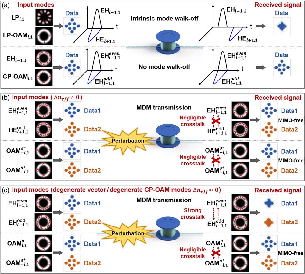
The concept and principle of a comparison among different spatial mode bases for finding the superior one are illustrated in Fig. 1. Four kinds of spatial mode bases in cylindrically symmetric fiber, i.e., vector modes, LP modes, LP-OAM modes, and CP-OAM modes, are considered for comparison and later system-level experimental demonstration.
![]()
Figure 1.Concept and principle of a comparison among different spatial mode bases (LP, LP-OAM, vector, and CP-OAM) in ACF. (a) Intrinsic mode walk-off for LP/LP-OAM modes and no mode walk-off for vector/CP-OAM modes. (b) Data-carrying MDM transmission using spatial modes with large
In the case of high-order vector modes, the electric fields of HE and EH modes can be described as
Remarkably, in cylindrically symmetric fiber, the four kinds of spatial mode bases (vector modes, LP modes, LP-OAM modes, and CP-OAM modes) can be deduced from each other. For instance, both LP modes and OAM modes can be synthesized from the linear combination of vector modes of the fiber.
In the case of high-order LP modes, the general relationship between LP modes and vector modes can be written as
From Eqs. (1) and (2), one can find that LP modes are composed of two different fiber vector modes, which have different propagation constants () in fiber with a relatively high-contrast index, such as ACF. When propagating along such fiber supporting nondegenerate HE and EH modes, the LP mode bases will suffer from the intrinsic walk-off effect after propagation even without any perturbation, as illustrated in Fig. 1(a).
In the case of high-order LP-OAM modes, they can be regarded as a superposition of two LP modes with a phase difference (weakly guiding fiber) from the formula. In fact, LP-OAM modes are the linear combination of all four vector modes (even HE, odd HE, odd EH, and even EH) as follows:
In the case of high-order CP-OAM modes, the relationship between CP-OAM modes and vector modes can be expressed as
Remarkably, fiber perturbations are inevitable in practical deployment of optical fibers, such as bending, twisting, pressing, winding, moving, and various environmental disturbances, which may cause coupling between spatial modes. In general, the power coupling coefficient between any two spatial modes ( and ) under the fiber perturbation can be expressed as41,45
Intuitively, from the first term in Eq. (9), the mode coupling is maximized for degenerate modes when . It also implies that the mode coupling can be effectively reduced by increasing the propagation constant difference () or the mode effective refractive index difference (), which is achievable with proper fiber structure design. For the ACF in this work, the high-contrast-index design enables effective mode separation not only for modes in different mode groups () but also for high-order HE and EH modes in each mode group (), leading to weak mode coupling, as illustrated in Fig. 1(b). From the second term in Eq. (9), when , the integral becomes zero and there is no mode coupling; when , the nonzero integral value contributes to the mode coupling. Hence, the available angular momentum component and its coefficient of the transverse perturbation have an impact on the mode coupling. Particularly, even for the degenerate modes with the same propagation constant and mode effective refractive index, such as and or and , the mode coupling can be still negligible if the transverse perturbation does not contain sufficient angular momentum component to meet the condition of . This is actually possible, especially for high-order CP-OAM modes with the large value of . The mode coupling between and or between and requires a transverse perturbation component of , which is not easy to achieve for large . It indicates the distinct mode stability property of high-order CP-OAM modes and the underlying mechanism rely on the laws of angular momentum conservation, even in the case of fiber perturbations.
Among various fiber perturbations, moving or lifting the fiber out of the plane (i.e., out-of-plane fiber movement) is of great interest, since it introduces an extra Pancharatnam–Berry phase, also known as the geometric phase.43,44 It is associated with the topological nature, which is different from the conventional propagation dynamic phase dependent on the fiber length. For single-mode fiber (SMF) configured in an out-of-plane route with circular polarization input light, the output light beam acquires the geometric phase as46,47
For fibers supporting high-order modes, e.g., ACF in this work, the interesting geometric phase phonomenon also exists, and the geometric phase is extended to be related to both SAM () and OAM () carried by light beams, which can be written as48
For high-order CP-OAM modes passing through the perturbed fiber, the perturbed output modes adding the extra geometric phase can be expressed as
For high-order vector modes (formed by the linear combination of CP-OAM modes) passing through the perturbed fiber, the perturbed output modes can be regarded as the linear combination of perturbed CP-OAM modes expressed as
From Eqs. (12) and (13), one can clearly see that the out-of-plane fiber movement only introduces extra geometric phase to the CP-OAM modes themselves without leading to mode coupling, as depicted in Fig. 1(c). In contast, such an out-of-plane fiber movement causes significant mode coupling between degenerate even and odd vector modes ( and or and ), as shown in Fig. 1(c).
From a system-level point of view, when carrying data information on each spatial mode for MDM fiber-optic communications, the walk-off effect and perturbation-induced mode coupling phenomenon can significantly degrade the signal quality and resultant system performance. As shown in Fig. 1(a), for LP and LP-OAM mode bases, the intrinsic walk-off effect can cause a distorted mode profile at the receiver, and the transmitted signal spreads temporally even for a single-channel transmission through an ideal fiber without any perturbation. For vector and CP-OAM mode bases, there is no walk-off effect and no signal spreading for a single-channel transmission. As shown in Fig. 1(b), for modes with a large mode effective refractive index difference (), e.g., high-order HE and EH modes, and modes, and OAM modes with different , the mode coupling is suppressed, and MIMO-free data-carrying MDM transmission using these modes is available. As shown in Fig. 1(c), for degenerate even and odd vector modes in the vector mode basis, e.g., and , and , the out-of-plane fiber movement can cause mode coupling by an extra geometric phase, and MIMO-DSP is desired to mitigate the mode cross talk for data-carrying MDM transmission using vector modes. For degenerate and modes or degenerate and modes in the CP-OAM mode basis, the mode coupling decreases with the increase of and is negligible for large owing to the angular momentum conservation condition, which is not easily satisfied, leading to MIMO-free data-carrying MDM transmission. Meanwhile, the CP-OAM mode basis is also stable with negligible mode coupling under the out-of-plane fiber movement. In the following proof-of-concept system-level experiments, we choose several kinds of perturbations (bending, twisting, pressing, winding, and moving) as representative examples. We first loosely prepare a fiber spool to release the stress and minimize perturbations, i.e., for approximation of fiber without perturbation. We employ an in-line polarization controller (PC) on the ACF and adjust it to emulate relatively complicated perturbations including pressing, twisting, and slight out-of-plane fiber movement. We manually lift the fiber out of plane (out-of-plane fiber movement) to introduce a significant geometric phase. We put weight on the fiber to add pressure. We also wind the fiber into small circles, which includes bending, slight twisting, and slight out-of-plane fiber movement.
3 Experimental Implementation
In the system-level experiments to find the superior mode basis for MDM fiber-optic communications, we employ a 1-km ACF and compressively compare the transmission performance of different spatial mode bases (vector modes, LP modes, LP-OAM modes, and CP-OAM modes). The designed and fabricated ACF features an air core at the fiber center, and the modes are confined within the ring-structure high-index region with the outer cladding. The air core also plays a role as the inner cladding with enhanced index contrast. The measured refractive index profile of the ACF is shown in Fig. 2(a). The radius of the air core is , and the outer radius of the ring-structure region is . The ACF is fabricated by the standard modified chemical vapor deposition method. The ring-structure design benefits the supression of high-order radial modes. The high-index contrast between the ring-structure and cladding helps to lift the mode degeneracy of OAM modes, including high-order HE and EH modes, and modes with the same , and OAM modes with different . The between adjacent OAM modes within each OAM mode group for is depicted in Fig. 2(b). It should be noted that OAM modes with different (i.e., different OAM mode groups) have large (). Particularly, in each mode group, HE and EH modes, or and modes with the same , also have a relatively large (), which increases with and helps to suppress the mode coupling. Such a distinct feature, which is not available in conventional weakly guiding fibers, is gained by the high-contrast-index ring-structure design of the ACF. The basic experimental setup is shown in Fig. 2(c). Spatial light modulators (SLMs) are used to generate LP modes or LP-OAM modes by properly switching the loaded phase patterns. Several typical examples of phase patterns loaded onto the SLMs are depicted in the insets of Fig. 2(c). The polarizers are aligned to the working direction of SLMs, and the proper adjustment of polarization states in the transmitters [not shown in Fig. 2(c)] optimizes the power. To generate CP-OAM modes, quarter-wave plates (QWPs) are added to convert the linear polarization to circular polarization (i.e., LP-OAM to CP-OAM). To generate vector modes, the QWP is replaced with a q-plate. Since the q-plate can convert CP Gaussian mode to CP OAM mode with reversed SAM, it can also produce vector modes with linear polarization inputs. This is because the vector modes can be regarded as the linear combination of CP-OAM modes, and the LP input can be decomposed into the left-handed CP (LCP) and right-handed CP (RCP) components. In this case, the phase patterns loaded onto SLMs are changed to gratings, and SLMs function as mirrors. At the receiver side, another SLM loaded with specific phase patterns is used to detect the LP and OAM modes, i.e., converting back to Gaussian-like beams and coupling to fibers for detection. To detect LP and LP-OAM modes, the QWP is replaced with a half-wave plate (HWP) to optimize the polarization direction. To detect CP-OAM modes, the QWP converts the linear polarization back from the circular polarization (i.e., CP-OAM to LP-OAM). To detect vector modes, the QWP is replaced with a q-plate. To characterize the basic properties of different mode bases, only a single channel is used at the transmitter side in the experimental setup. To carry out the system-level experiments of MDM fiber-optic communications, two channels are used at the transmitter side for proof-of-concept demonstration, where a beam splitter (BS) is simply used to combine the two data channels and is coupled into the fabricated 1-km ACF via an objective lens (OL). An in-line PC is put on the ACF to induce one kind of fiber perturbation. Other kinds of fiber perturbations are exerted by pressing the fiber, winding the fiber into small circles, and lifting the fiber out of plane. The measured fiber facet microscope image of the fabricated ACF is shown in the inset of Fig. 2(c). After single-channel transmission or two-channel MDM transmission through the 1-km ACF, LP modes (by SLM), LP-OAM modes (by SLM), CP-OAM modes (by QWP and SLM), and vector modes (by q-plate) are converted back to Gaussian-like modes for detection. For system-level single-channel transmission or MIMO-free two-channel MDM transmission experiments, only one set of detection at the receiver side is required (one after another detection for MIMO-free MDM). For two-channel MDM transmission with significant mode coupling and cross talk, two sets of detection are required to simultaneously receive two-channel signals with mutual cross talk.
![]()
Figure 2.Characterization of the ACF and experimental setup for spatial modes transmission in ACF. (a) Measured refractive index profile of the ACF. (b) The
3.1 Characterization of Different Spatial Mode Bases
First, we characterize basic properties of different spatial mode bases when they propagate through the ACF. Figures 3(a)–3(d) show measured typical intensity profiles of LP, LP-OAM, CP-OAM, and vector modes, respectively. The LP modes feature petal-like patterns. The LP-OAM, CP-OAM, and vector modes show doughnut-shaped intensity profiles due to phase and polarization singularities at the beam center. We measure the stability of different spatial mode bases (LP, LP-OAM, CP-OAM, and vector modes) in ACF (see Figs. 4–8). The LP and LP-OAM modes are not stable and easy to convert to each other after fiber propagation (see Figs. 4 and 5). Figures 3(a) and 3(b) show captured images in an instant. To verify the CP-OAM modes, we use a polarization beam displacer (PBD) after the QWP at the receiver side to detect the circular polarization [not shown in Fig. 2(c)]. Meanwhile, the OAM orders are measured by the interference with an expanded reference Gaussian beam, as shown in Fig. 3(c). The number of twists and the twisting direction determine the magnitude and sign of OAM orders. The CP-OAM modes, including the degenerate CP-OAM modes within a mode group, are stable under fiber perturbations as analyzed above (see Figs. 7 and 8). To verify the vector modes, we use a rotating polarizer [not shown in Fig. 2(c)] and the observed petal-like patterns after the polarizer confirm the generation of vector modes, as shown in Fig. 3(d). The vector modes can be converted back to Gaussian-like beams by the q-plate. The degenerate even and odd vector modes are not stable under out-of-plane fiber movement perturbations (see Fig. 6).
![]()
Figure 3.Basic properties of spatial modes transmission in ACF. (a)–(d) Measured intensity profiles of different spatial modes after 1-km ACF transmission. (a)
![]()
Figure 4.Measured intensity profiles of LP mode and its coupled mode after transmission in ACF. Easy coupling is observed (
![]()
Figure 5.Measured intensity profiles of LP-OAM mode and its coupled mode after transmission in ACF. Easy coupling is observed (
![]()
Figure 6.Measured intensity profiles of vector mode and its coupled degenerate vector mode (after demodulation by a q-plate to Gaussian-like beam with bright spot at the beam center) after transmission in ACF under out-of-plane fiber movement perturbation. Easy coupling is observed (
![]()
Figure 7.Measured intensity profiles of CP-OAM mode and its coupled degenerate CP-OAM mode after transmission in ACF under out-of-plane fiber movement perturbation. Negligible coupling is observed (
![]()
Figure 8.Measured intensity profiles of CP-OAM mode (interference with a reference Gaussian beam) and its coupled degenerate CP-OAM mode (interference with a reference Gaussian beam) after transmission in ACF under out-of-plane fiber movement perturbation. Negligible coupling is observed (
We investigate the walk-off effect of different spatial mode bases by employing a pulsed laser source. The period of the pulsed laser is 12.5 ns, which is larger than the DGD among different modes after passing through the 1-km ACF. This ensures that the walk-off pulse and the periodically repeating pulse are easily distinguished. Figures 3(e)–3(j) show measured temporal waveforms by an oscilloscope (pulse response) after 1-km ACF transmission when launching LP, LP-OAM, vector, and CP-OAM modes to the ACF. ACF transmissions without and with perturbations are measured. Figures 3(e) and 3(f) show measured results for and modes, respectively, without fiber perturbations. One can clearly see two splitting pulses, showing the walk-off effect of LP and LP-OAM modes even without fiber perturbations. These are because both LP and LP-OAM modes are composed of non-degenerate HE and EH modes with different propagation constants. The two splitting pulses have a measured time interval of about 1.13 ns ( and ) in Figs. 3(e) and 3(f), which are in good agreement with the theory (DGD between and : ). Figures 3(g) and 3(h) show measured results for and modes, respectively, without fiber perturbations. Only one single pulse is observed after 1-km ACF transmission, showing no walk-off effect. Particularly, even under fiber perturbations (e.g., out-of-plane fiber movement), one can still only observe one single pulse after 1-km ACF transmission for and modes, as shown in Figs. 3(i) and 3(j), respectively, which are consistent with the theory.
Despite no walk-off effect, the degenerate even and odd vector modes can easily couple with each other due to an extra geometric phase induced by out-of-plane fiber movements, which cannot be seen from the pulse response measurement in Fig. 3(i). In the experiment, for the vector mode basis, we employ a PBD after the q-plate to split and simultaneously detect the power of even and odd vector modes by a camera. As a result, we can measure the relative power of even and odd vector modes under out-of-plane fiber movements. As shown in Fig. 3(k) (launching mode: ), significant power coupling between and is observed, and complete mode coupling is possible. In contrast, for the CP-OAM mode basis, we also use a PBD after the QWP to split and simultaneously detect the relative power of degenerate CP-OAM modes by a camera under out-of-plane fiber movements. As shown in Fig. 3(l) (launching mode: ), negligible power coupling between and modes is observed. The power of coupled mode remains <−15 dB compared to that of the launched mode. The measured results in Figs. 3(k) and 3(l) indicate that the degenerate vector modes are susceptible, while the degenerate high-order CP-OAM modes are stable against the out-of-plane fiber movement perturbations.
3.2 Single-Channel Transmission with Different Spatial Modes
Second, we comprehensively evaluate the system-level BER performance for data-carrying single-channel transmission over the 1-km ACF with different spatial modes. For the single-channel system-level demonstration, the details of the transmitter and receiver in Fig. 2(c) are shown in Fig. 9(a). At the transmitter, a continuous-wave laser at 1550 nm is modulated by an in-phase/quadrature (I/Q) modulator driven by an arbitrary waveform generator (AWG) to generate a 12.5-Gbaud 8-ary quadrature amplitude modulation (8-QAM) signal. An erbium-doped fiber amplifier (EDFA) and a PC are used to boost the power and adjust the polarization state of the optical signal. At the receiver, the optical signal is amplified by an EDFA. A variable optical attenuator (VOA) followed by another EDFA is used to adjust the received optical signal-to-noise ratio (OSNR) for BER measurement. Another laser serves as the local oscillator (LO) to mix with the received optical signal by an optical hybrid, the outputs of which are sent to an oscilloscope followed by the offline DSP. Figure 9(b) plots the measured BER curves for data-carrying single-channel transmission over the 1-km ACF with LP mode, LP-OAM mode, vector mode, and CP-OAM mode. Two sets of BER curves are measured, i.e., one without fiber perturbations (solid markers) and the other with fiber perturbations (hollow markers) by adjusting the in-line PC on the ACF. For LP and LP-OAM modes, the measured BER values are always far above the soft-decision forward-error correction (SD-FEC) threshold of , whether or not fiber perturbations are induced. These are due to the intrinsic walk-off effect of LP and LP-OAM modes and accompanied mode coupling. For vector modes, the measured BER values show excellent performance without fiber perturbations. Some performance degradation, with an OSNR penalty of compared to the case without fiber perturbations, is observed for vector modes under fiber perturbations by adjusting the in-line PC. This might be ascribed to the power coupling of vector modes under fiber perturbations. However, the BER values can be still below the hard-decision forward-error correction (HD-FEC) threshold of . For CP-OAM modes, one can clearly see very similar BER performance for 1-km ACF transmission without and with fiber perturbations. The measured OSNR penalties are only about 1 dB compared to the back-to-back case at a BER of (SD-FEC threshold). Figure 9(c) shows measured typical constellations for LP mode, LP-OAM mode, vector mode, and CP-OAM mode after 1-km ACF transmission as well as the back-to-back case.
![]()
Figure 9.Transmitter, receiver, and system-level performance for data-carrying single-channel transmission in ACF with different spatial modes. (a) Experimental configuration of the transmitter and receiver. AWG, arbitrary waveform generator; 8-QAM, 8-ary quadrature amplitude modulation; I/Q modulator, in-phase/quadrature modulator; EDFA, erbium-doped fiber amplifier; PC, polarization controller; VOA, variable optical attenuator; LO, local oscillator. (b) Measured BER curves for LP, LP-OAM, vector, and CP-OAM modes without and with fiber perturbations. OSNR, optical signal-to-noise ratio; HD-FEC, hard-decision forward-error correction (
To further show the impact of different kinds of fiber perturbations on data-carrying single-channel transmission over the 1-km ACF, we also measure the BER performance with each kind of varied fiber perturbation (i.e., dynamic BER performance under each kind of fiber perturbation). Four typical kinds of fiber perturbations are taken into consideration in the experiment, i.e., adjusting the in-line PC (pressing, twisting, and slight out-of-plane fiber movement), significant out-of-plane fiber movement, putting weight on the fiber to add pressure (pressing) (maximum weight: 1.62 kg), and winding the fiber into small circles (bending, slight twisting, and slight out-of-plane fiber movement) (0 to 4 circles, 12.7-mm diameter for each circle). The initial value of OSNR is set to 16 dB. The measured results for LP7,1 mode, LP-OAM7,1 mode, EH6,1 vector mode, and CP-OAM7,1 mode under different kinds of fiber perturbations are shown in Figs. 9(d)–9(g), respectively. One can see the measured BER values for LP and LP-OAM modes are always above the HD-FEC threshold () even for the single-channel transmission, showing severely degraded performance. For vector modes, as shown in Fig. 9(f), the BER performance remains almost unchanged under the pressure perturbation (in-plane perturbation). However, the BER performance for vector modes suffers some degradation under other kinds of fiber perturbations, such as adjusting the in-line PC, significant out-of-plane movement, and winding the fiber into small circles, as shown in Figs. 9(d), 9(e), and 9(g). Under the varied fiber perturbations, the BER values can be above the HD-FEC threshold (). These could be explained with the fact that fiber perturbations with out-of-plane movements cause the power coupling of vector modes. Remarkably, as shown in Figs. 9(d)–9(g), the BER performance for CP-OAM modes stays almost unchanged and always below the HD-FEC threshold () under all kinds of varied fiber perturbations.
The measured system-level results for data-carrying single-channel transmission indicate that the CP-OAM mode basis shows impressive performance against various kinds of fiber perturbations. This implies the great potential for using the CP-OAM mode basis in MDM fiber-optic communications.
3.3 Two-Channel MDM Transmission Using Vector Modes and CP-OAM Modes
Third, we comprehensively assess the system-level BER performance for data-carrying two-channel MDM transmission over the 1-km ACF using vector modes and CP-OAM modes. Since LP and LP-OAM modes show significantly worse BER performance compared to vector and CP-OAM modes in data-carrying single-channel transmission systems, for the following MDM transmission system, we only focus on the comparison between vector and CP-OAM modes and choose two-channel MDM transmission for simple proof-of-concept demonstration. For the two-channel MDM system-level demonstration, the details of the transmitter, receiver, and MDM configuration are shown in Figs. 10(a)–10(d). At the transmitter, as shown in Fig. 10(a), a 10-Gbaud quadrature phase-shift keying (QPSK) signal or a 12.5-Gbaud 8-QAM signal is prepared, which is divided into two paths with one path delayed by a 1-km SMF compared to the other for decorrelation. As a result, two-channel signals are generated, with their power boosted by EDFAs. At the receiver, for the MIMO-free MDM transmission with negligible mode coupling (e.g., CP-OAM modes), only one set of detection is required, as depicted in Fig. 2(c). For the MIMO-DSP enabled MDM transmission with significant mode coupling (e.g., degenerate vector modes), two sets of detection are required, as depicted in Fig. 10(b). Two-channel received signals with mode coupling after 1-km ACF transmission are mixed with the LO (10-GHz frequency offset compared to the signal) and detected by two photodetectors (PDs) based on the heterodyne coherent detection scheme. The received two-channel electrical signals after analog-to-digital conversion (ADC) are used for MIMO-DSP to mitigate the mode cross talk for BER performance measurement. Due to available lab conditions with a limited number of q-plates, we employ another two sets of loop structure to generate two-channel vector modes at the transmitter in the MDM transmission experiment, as shown in Fig. 10(d). At the receiver, two q-plates are used to convert the two-channel vector modes back to Gaussian-like beams, which are coupled to SMFs for detection. The loop structure incorporating a vortex phase plate (VPP) for the generation of vector modes is illustrated in Fig. 10(c). The operation principle still relies on the linear combination of two CP-OAM modes for the generation of vector modes. The incident LP Guassian beam is rotated to 45 deg linear polarization by an HWP. After passing through a polarization beam splitter (PBS), the Gaussian beam is divided into - and -polarization components, propagating along clockwise and counterclockwise directions, respectively. A polarization-independent VPP incorporated into the loop structure adds a spiral phase front to the Gaussian beam and converts it to the OAM beam. Note that the VPP generates two LP-OAM modes with inversed sign for clockwise and counterclockwise propagation beams. The - and -polarization OAM modes are combined again by the PBS followed by a QWP. Both - and -polarization OAM modes experience twice the reflections by the mirror or PBS, so the sign of their OAM orders remains inversed. The QWP further converts the - and -polarization OAM modes with inversed sign to two CP-OAM modes with inversed OAM charge, respectively. As a result, the vector mode synthesized by two CP-OAM modes is generated. Particularly, different kinds of vector modes, including the degenerate even and odd ones ( and or and ), can be generated by properly adjusting the axis of the QWP. It is worth noting that the proposed loop structure scheme for the generation of vector modes in Fig. 10(c) has the distinct advantages of high quality and high stability. This is because the clockwise and counterclockwise propagation beams in the loop structure share the same path, and the generation scheme is stable and robust against environmental disturbance.
![]()
Figure 10.Transmitter, receiver, loop structure, setup, and system-level performance for data-carrying two-channel MDM transmission in ACF with degenerate vector modes and degenerate CP-OAM modes (SAM and OAM anti-aligned). (a) Transmitter. AWG, arbitrary waveform generator; 8-QAM, 8-ary quadrature amplitude modulation; QPSK, quadrature phase-shift keying; I/Q modulator, in-phase/quadrature modulator; EDFA, erbium-doped fiber amplifier; VOA, variable optical attenuator; OC, optical coupler; SMF, single-mode fiber. (b) Receiver. PC, polarization controller; LO, local oscillator; PD, photodetector; ADC, analog-to-digital converter; MIMO-DSP, multiple-input multiple-output digital signal processing. (c) Loop structure incorporating a VPP for the generation of vector modes. VPP, vortex phase plate; PBS, polarization beam splitter; QWP, quarter-wave plate. (d) Experimental configuration for two-channel MDM transmission in ACF with degenerate vector modes. LO, local oscillator. (e) Measured BER curves for MDM transmission in ACF with degenerate even and odd vector modes under out-of-plane fiber movement perturbation. (f) Measured BER curves for MIMO-free MDM transmission in ACF with degenerate CP-OAM modes under out-of-plane fiber movement perturbation. Insets, constellations of 8-QAM signals. (g)–(i) Measured dynamic BER performance under each kind of varied fiber perturbation. (g) Adjusting the in-line PC and out-of-plane fiber movement; (h) putting weight on the fiber to add pressure; (i) winding the fiber into small circles.
Figure 10(e) plots the measured BER curves for data-carrying (10-Gbaud QPSK signal) two-channel MDM transmission over the 1-km ACF using degenerate even and odd vector modes (e.g., and modes) under out-of-plane fiber movement perturbations. The mode cross talk is inevitable due to the geometric phase caused by out-of-plane fiber movement perturbations. The amount of mode cross talk is controllable by properly changing the degree of fiber perturbations. In the experiment, we adjust the degree of lifting the fiber out of plane to introduce two sets of mode cross talk value, i.e., one with moderate cross talk and the other with 0 dB severe cross talk. For the moderate cross talk, the BER values of two channels are above the HD-FEC threshold (). Hence, MIMO-DSP is especially required to mitigate the cross talk to be used in MDM fiber-optic communications at the price of increased complexity and DSP-induced power consumption. In particular, for the severe cross talk, the BER performance after MDM transmission gets even worse. The mode cross talk cannot be mitigated even if the MIMO-DSP is applied. These set great limitations on MDM transmission using degenerate even and odd vector modes under fiber perturbations.
Figure 10(f) plots the measured BER curves for data-carrying (12.5-Gbaud 8-QAM signal) two-channel MDM transmission over the 1-km ACF using degenerate CP-OAM modes (e.g., and ) under out-of-plane fiber movement perturbations. Remarkably, MIMO-free MDM transmission is achieved due to the intrinsic high stability of degenerate CP-OAM modes (low-level cross talk of about ), leading to superior performance with only OSNR penalty compared to the back-to-back case at a BER of (HD-FEC threshold). The insets of Fig. 10(f) show typical constellations of 8-QAM signals.
For data-carrying MDM transmission with degenerate and modes, we also measure the dynamic BER performance under each kind of varied fiber perturbation. The initial value of OSNR is set to 16 dB. Figure 10(g) depicts the dynamic BER performance by adjusting the in-line PC and under out-of-plane fiber movement. Figure 10(h) displays the dynamic BER performance by putting weight on the fiber to add pressure. Figure 10(i) shows the dynamic BER performance by winding the fiber into small circles. For all kinds of fiber perturbations, the measured results show impressive BER performance for MDM transmission using degenerate and modes without the need of MIM-DSP.
In addition to degenerate and modes with the SAM and OAM anti-aligned (i.e., linear combination of and modes), we also consider the data-carrying (12.5-Gbaud 8-QAM signal) two-channel MDM transmission over the 1-km ACF using another kind of degenerate CP-OAM modes, i.e., degenerate and modes with the SAM and OAM aligned (linear combination of and modes). The measured BER curves and typical constellations under out-of-plane fiber movement are shown in Fig. 11(a). For other kinds of fiber perturbations, such as adjusting the in-line PC, the measured dynamic BER performance is depicted in Fig. 11(b). Favorable operation performance is achieved using degenerate and modes for MIMO-free MDM transmission.
![]()
Figure 11.System-level performance for data-carrying two-channel MDM transmission in ACF with degenerate CP-OAM modes (SAM and OAM aligned) from the same mode group or CP-OAM modes from different mode groups. (a), (b) Degenerate CP-OAM modes (SAM and OAM aligned) from the same mode group. (a) Measured BER curves for MIMO-free MDM transmission in ACF with degenerate CP-OAM modes under out-of-plane fiber movement perturbation. Insets, constellations of 8-QAM signals. (b) Measured dynamic BER performance when adjusting the in-line PC. (c)–(g) CP-OAM modes from different mode groups. (c) Measured BER curves for MIMO-free MDM transmission in ACF with CP-OAM modes under fiber perturbation. (d)–(g) Measured dynamic BER performance under each kind of varied fiber perturbation. (d) Adjusting the inline PC and out-of-plane fiber movement; (e) out-of-plane fiber movement; (f) putting weight on the fiber to add pressure; (g) winding the fiber into small circles.
The two-channel OAM modes in Figs. 10(f)–10(i) or Figs. 11(a) and 11(b) are within the same mode group. Additionally, we also study the data-carrying (12.5-Gbaud 8-QAM signal) two-channel MDM transmission over the 1-km ACF using two CP-OAM modes from different mode groups (e.g., and modes). Figure 11(c) plots the measured BER curves and typical constellations under out-of-plane fiber movement. Less than 1-dB OSNR penalty compared to the back-to-back case at a BER of (HD-FEC threshold) is achieved for MIMO-free MDM transmission with and modes. Figures 11(d)–11(g) depict the dynamic BER performance under each kind of varied fiber perturbation (initial value of OSNR: 16 dB), i.e., adjusting the in-line PC [Fig. 11(d)], under out-of-plane fiber movement [Fig. 11(e)], putting weight on the fiber to add pressure [Fig. 11(f)], and winding the fiber into small circles [Fig. 11(g)]. The measured results in Figs. 11(c)–11(g) indicate outstanding performance for MIMO-free MDM transmisison using CP-OAM modes from different mode groups. This can be briefly explained as follows. On one hand, CP-OAM modes from different mode groups are not degenerate with large , which is beneficial to suppress the mode cross talk; on the other hand, the CP-OAM mode in each mode group is also stable itself without power loss (i.e., power coupling to other degenerate CP-OAM mode within the same mode group).
The experimental results in Figs. 3 and 9–11 are for 1-km ACF based on the existing laboratory conditions, and CP-OAM modes show high stability and robustness against various fiber perturbations. It is expected the transmission stability might also be maintained for longer ACF (e.g., 10-km ACF) considering the following aspects.
The perturbations (bending, twisting, pressing, winding, and moving) applied to the fiber in the experiment are significant. That is, the impact of applied fiber perturbations on the communication performance is greater than the impact of fiber imperfections. Hence, for longer ACF, especially with future improved fiber fabrication technique and optimized fiber performance, one would still expect high transmission stability and robustness against fiber perturbations.
According to the theoretical analyses from Eqs. (6)–(9), for the ACF used in the experiment, the high-contrast-index design with ACF structure facilitates significant mode separation both for CP-OAM modes from different mode groups () and for high-order nondegenerate CP-OAM modes in each mode group, which are beneficial to maintain the transmission stability for longer ACF. Due to the angular momentum conservation condition, which is not easily satisfied, the mode coupling between degenerate CP-OAM modes within the same mode group is also negligible, especially for large . Moreover, based on the theoretical analyses from Eqs. (10)–(12), the local out-of-plane fiber movement perturbation (i.e., moving or lifting the fiber out of the plane) only introduces an extra geometric phase to the CP-OAM modes themselves but does not cause mode coupling between degenerate CP-OAM modes within the same mode group, which is also independent of fiber length. Thus the transmission stability is expected to be maintained for 10 km or an even longer ACF.
In practical applications with possible unpredictable or more complex fiber perturbations, even if the transmission stability for a 10 km or longer ACF might be degraded slightly, the superiority of CP-OAM modes could still be expected when compared to other mode bases (LP modes, vector modes, and LP-OAM modes). Meanwhile, in the present 1-km fiber transmission experiment, 8-QAM signals are employed in Figs. 10(f)–10(i) and Figs. 11(a)–11(g). For other modulation format signals, such as QPSK with large cross talk tolerance, one would expect the feasibility of MDM transmission over 10 km or an even longer ACF with favorable system performance.
In the experiment, we demonstrate the transmission stability for high-order CP-OAM modes, i.e., , as shown in Figs. 10 and 11. One would also expect the relatively good transmission stability for relatively low-order CP-OAM modes in the ACF, especially for CP-OAM modes from different mode groups. Remarkably, even if low-order CP-OAM modes in ACF have moderate transmission stability, the mode coupling may increase with the decrease of , especially for the lowest-order modes (e.g., ). One may also use modulation format signals with relatively large cross talk tolerance (e.g., QPSK). Meanwhile, small-scale simplified MIMO-DSP might be used to mitigate the mode cross talk between the lowest-order modes. With future improvement, flexible “mode engineering” (e.g., separation of the lowest-order modes) is expected to optimize the fiber structure to enhance the transmission stability of low-order modes, even for the lowest-order modes in fiber.
4 Discussions
4.1 Toward Practical Fiber Deployment with Complex Perturbations
In this work, we aim to find the superior mode basis for SDM/MDM fiber-optic communications in ACF. We give both theoretical analyses and system-level comparison in the experiment. We choose several representative fiber perturbations (bending, twisting, pressing, winding, and moving) in the proof-of-concept experiment, such as adjusting in-line PC (pressing, twisting, and slight out-of-plane fiber movement), significant out-of-plane fiber movement, putting weight on the fiber to add pressure (pressing), and winding the fiber into small circles (bending, slight twisting, and slight out-of-plane fiber movement). The obtained results show the superiority of the CP-OAM mode basis. Remarkably, in practical fiber deployment (cabling, installation, etc.) and realistic applications, more complex fiber perturbations would be encountered. From this point of view, more in-depth system-level studies are expected to further show the robustness of the CP-OAM mode basis in real application scenarios, such as data centers and high-performance computing with cabled ACF, especially under extreme working conditions.
4.2 Improved Fiber Design and Optimized Fiber Fabrication
The ACF employed in the experiment supports higher-order OAM modes and MIMO-free MDM transmission using degenerate CP-OAM modes up to the seventh order is demonstrated. From the above analyses, the mode stability of CP-OAM modes increases with the mode order based on the laws of angular momentum conservation. Improved fiber design (e.g., geometric parameters and refractive index profiles) supporting even higher-order OAM modes () is expected so that more spatial modes with higher mode stability can be used to more effectively scale the transmission capacity and enhance the robustness against various fiber perturbations. The fabricated ACF has relatively large propagation loss ( for and for ), mainly due to the high-contrast-index structure and fabrication imperfections. Future optimized fiber fabrication is expected to reduce the loss, considering the fact that some commercially available fibers, such as dispersion-compensating fibers also with high-contrast-index, show low-level loss around . This will benefit long-distance MDM fiber-optic communications using the optimized ACF.
4.3 Efficient and Scalable Mode (De)multiplexers
To facilitate MDM transmission with a large number of OAM modes, an efficient and scalable mode (de)multiplexer is a key device that functions similarly to the wavelength (de)multiplexers in wavelength-division multiplexing transmission systems. Fortunately, there have been many works on scalable OAM (de)multiplexers, such as OAM mode sorter based on the Cartesian to log-polar coordinate transformation,49 combination of log-polar coordinate mapping and refractive beam copying,50,51 spiral transformation,52 and multi-plane light conversion.53,54 These OAM mode (de)multiplexers can efficiently separate multiple OAM modes with different . However, additional discrete optical elements (e.g., lenses) are also required in the (de)multiplexing architecture. For MDM transmission in ACF with CP-OAM modes, a compact OAM mode (de)multiplexer is highly expected, with its input and output ports directly connected to the ACF and SMF array. Moreover, in order to take full use of all spatial modes, including OAM modes with the same in each mode group, e.g., and or and , OAM (de)multiplexers incorporating the SAM sorting function are desirable.
4.4 Superior Mode Basis in Diverse Fibers
There are many kinds of fibers widely used in SDM applications, such as FMF, MMF, RCF, ACF, multicore fiber (MCF), and multicore few-mode fiber. In this work, we mainly focus on the ACF and comprehensively study its superior mode basis for MDM transmission. We find the CP-OAM mode basis is the superior one in ACF for MDM transmission, especially for high-order CP-OAM modes. It is noted that the mode cross talk could be nonnegligible for low-order modes (e.g., and 1) and proper DSP might be still required to mitigate the cross talk. One would expect “mode engineering” with optimized fiber structure to further separate the low-order modes (i.e., large ). In addition to four kinds of spatial mode bases discussed in this work (i.e., LP modes, LP-OAM modes, vector modes, and CP-OAM modes), Eisenbud–Wigner–Smith states as principal modes in fibers have also attracted great interest.55,56 Moreover, enhanced spin–orbit interaction of light in highly confining optical fibers has also shown its potential in MDM transmission.25 For diverse fibers supporting multiple spatial modes, more theoretical and experimental works are expected to find the most suitable mode basis in a specific fiber. Additionally, more comprehensive evaluation criteria should be considered, such as capacity, distance, cross talk, BER performance, robustness, MIMO-free/MIMO-DSP, complexity, and power consumption.
4.5 Superior Mode Basis in Complex Transmission Media
Beyond MDM transmission in fibers, versatile spatial modes (Laguerre–Gaussian beams, Hermite–Gaussian beams, vector beams, Bessel beams, Airy beams, Mathieu beams, pin-like beams, bottle beams, customized beams, arbitrarily structured light, etc.) have been also widely applied to data transmission through complex media (free-space, underwater, chip, etc.).57 The spatial mode propagation in complex media is much more complicated compared to that in optical fibers. Diffraction, scattering, divergence, obstacle, turbulence, and other kinds of imperfections need to be considered. Different kinds of spatial modes also show their unique propagation properties, such as being diffraction-free, self-healing, non-line-of-sight, and turbulence-resilient.57,58 Very recently, turbulence-resilient pilot-assisted self-coherent free-space optical communications using automatic optoelectronic mixing of many modes,59 compensation-free high-dimensional free-space optical communications using turbulence-resilient vector beams,60 and robust vectorial structured light propagation in complex media61 have been proposed and demonstrated, showing impressive performance. In the future, more and more works are expected to find the superior mode basis for data transmission in complex media.
4.6 Extended Applications of Versatile Spatial Modes in Fibers
Beyond SDM/MDM fiber-optic communications using spatial modes, more extended applications of versatile mode bases in fibers are expected, such as spin–orbit mapping,62 optical activity,63 nonlinear optics,64 optical metrology,65 optical imaging,66 and quantum science.67,68 For example, spin–orbit mapping of light in an FMF originating from the mode degeneracy lifting, high-resolution wave meter by enhanced optical activity in fibers, intermodal nonlinear mixing with Bessel beams in fibers, remote measurement of the angular velocity vector based on vectorial Doppler effect using ACF, time-of-flight 3D imaging through multimode optical fibers, and high-dimensional quantum cryptography with hybrid OAM states through RCF have been proposed and demonstrated, showing favorable performance. In the future, one would expect to see more emerging applications using versatile mode bases in different kinds of fibers. The newly added space degree of freedom of spatial modes in fibers provides more advanced applications beyond conventional SMF.
5 Conclusion
In summary, we have presented theoretical analyses and system-level experimental demonstrations on finding the superior spatial mode basis for MDM fiber-optic communications in ACF. The LP and LP-OAM modes have intrinsic mode walk-off effect, causing split pulse response and signal spreading as well as mode coupling. Despite no intrinsic mode walk-off effect, the degenerate even and odd vector modes ( and or and ) can easily couple to each other due to extra geometric phase induced by out-of-plane fiber movements. In contrast, CP-OAM modes show high stability and robustness against various fiber perturbations, including high-order degenerate CP-OAM modes within the same mode group. Such superiority originates from the laws of angular momentum conservation. Particularly, we comprehensively compare the system-level BER performance for data-carrying single-channel and two-channel MDM transmission over the 1-km ACF with different spatial modes. Various kinds of fiber perturbations are considered, such as adjusting the in-line PC (pressing, twisting, and slight out-of-plane fiber movement), significant out-of-plane fiber movement, putting weight on the fiber to add pressure (pressing), and winding the fiber into small circles (bending, slight twisting, and slight out-of-plane fiber movement). The measured results indicate that LP and LP-OAM modes suffering mode walk-off and coupling are not suitable for data transmission in ACF; degenerate even and odd vector modes need MIMO-DSP with increased complexity to mitigate the moderate cross talk and may fail to recover the signal with severe cross talk for MDM transmission in ACF; high-order CP-OAM modes show impressive performance for MDM transmission in ACF under various kinds of fiber perturbations. The system-level demonstration shows that the CP-OAM mode basis is the superior one for MDM fiber-optic communications with ACF, which may find promising applications in short-reach MDM optical interconnects for data centers and high-performance computing. For the future, finding a superior mode basis in various kinds of fibers and other complex transmission media as well as extending more advanced applications with versatile spatial modes in fibers would be of great interest.
Jian Wang received his PhD in physical electronics from Wuhan National Laboratory for Optoelectronics, Huazhong University of Science and Technology, China, in 2008. He worked as a postdoctoral research associate in the Optical Communications Laboratory at the University of Southern California, United States, from 2009 to 2011. Currently, he is a professor at Wuhan National Laboratory for Optoelectronics, Huazhong University of Science and Technology, China. He is vice director of Wuhan National Laboratory for Optoelectronics, Huazhong University of Science and Technology, China. He was elected as an OPTICA fellow (formerly OSA fellow) in 2020, and SPIE fellow in 2022. He leads the Multi-dimensional Photonics Laboratory. His research interests include optical communications, optical signal processing, silicon photonics, photonic integration, OAM, and structured light.
Biographies of the other authors are not available.
References
[18] J. Wang. Advances in communications using optical vortices. Photonics Res., 4, B14-B28(2016).
[20] J. Wang. Data information transfer using complex optical fields: a review and perspective. Chin. Opt. Lett., 15, 030005(2017).
[43] Z. Ma et al. Robustness of OAM fiber modes to geometric perturbations, SW3K.1(2018).
[53] N. K. Fontaine et al. Laguerre–Gaussian mode sorter. Nat. Commun., 10, 1865(2019).
[62] L. Fang et al. Spin-orbit mapping of light. Phys. Rev. Lett., 127, 233901(2021).

Set citation alerts for the article
Please enter your email address
© Copyright 2018-2021 | Chinese Laser Press. All Rights Reserved 沪ICP备15018463号-20