• Advanced Photonics Nexus
  • Vol. 2, Issue 1, 016006 (2023)
Zhiwei Guo1、*, Xian Wu1, Yong Sun1、*, Haitao Jiang1, Ya-Qiong Ding2, Yunhui Li1, Yewen Zhang1, and Hong Chen1、*
Author Affiliations
  • 1Tongji University, Key Laboratory of Advanced Microstructure Materials, School of Physics Science and Engineering, Shanghai, China
  • 2University of Shanghai for Science and Technology, Science College, Shanghai, China
  • show less
    DOI: 10.1117/1.APN.2.1.016006 Cite this Article Set citation alerts
    Zhiwei Guo, Xian Wu, Yong Sun, Haitao Jiang, Ya-Qiong Ding, Yunhui Li, Yewen Zhang, Hong Chen. Anomalous broadband Floquet topological metasurface with pure site rings[J]. Advanced Photonics Nexus, 2023, 2(1): 016006 Copy Citation Text show less
    Schematics of the photonic pseudospin in the coupled ring system. (a) Reversal of pseudo-spin in forward coupling. (b) Consistency of pseudo-spins in the process of backward coupling. The upper (lower) row denotes pseudo-spin-down (up) mode. RHM and LHM are marked by pink and yellow, respectively.
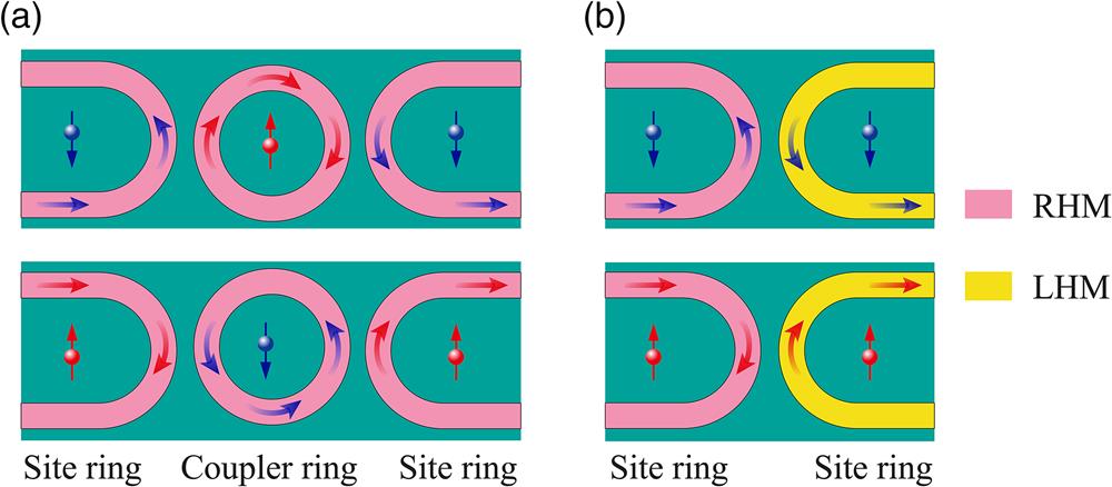
    Fig. 1. Schematics of the photonic pseudospin in the coupled ring system. (a) Reversal of pseudo-spin in forward coupling. (b) Consistency of pseudo-spins in the process of backward coupling. The upper (lower) row denotes pseudo-spin-down (up) mode. RHM and LHM are marked by pink and yellow, respectively.
    Realization of circuit-based LHM. (a) Schematic of circuit-based LHM realized in the TL platform; the structural parameters are given in Supplementary Material. (b) TL model of the circuit-based LHM. (c) Corresponding circuit model of the effective LHM.
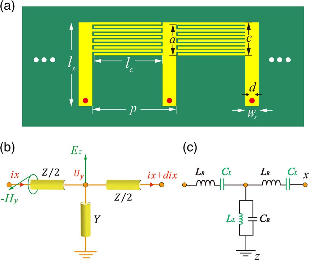
    Fig. 2. Realization of circuit-based LHM. (a) Schematic of circuit-based LHM realized in the TL platform; the structural parameters are given in Supplementary Material. (b) TL model of the circuit-based LHM. (c) Corresponding circuit model of the effective LHM.
    Schematic of anomalous Floquet topological insulator based on CRLH ring resonators. The size of our fabricated sample is 4×5 unit cells. The RHM (simple line strips) and left-handed material (complex branched strips) connect successively in a ring structure. The zoom-in picture of different ring resonators is presented on the top. The arrows represent the coupling direction of the energy flow in two materials with different handedness. The upper metallic microstrip and the lower dielectric substrate are marked by yellow and green, respectively.
    Fig. 3. Schematic of anomalous Floquet topological insulator based on CRLH ring resonators. The size of our fabricated sample is 4×5 unit cells. The RHM (simple line strips) and left-handed material (complex branched strips) connect successively in a ring structure. The zoom-in picture of different ring resonators is presented on the top. The arrows represent the coupling direction of the energy flow in two materials with different handedness. The upper metallic microstrip and the lower dielectric substrate are marked by yellow and green, respectively.
    Band structure and the edge states of the anomalous Floquet topological insulator. (a) Schematic of couplings between neighboring resonance rings, where the wave amplitude relations are marked by red arrows. (b) Configuration of U−U waveguide structure. The incident wave with high performance is coupled to the transmitted port based on the wave vector conservation condition for back direction. (c) Simulated backward coupling between RHM and LHM waveguides. (d) The value of coupling strength θ (red line) and the corresponding coupling phase (blue dashed line) can be derived from the U−U shape structure. (e) The projected band diagram of a semi-infinite strip-coupled ring lattice, whose width is finite in the y direction (N=30) and periodic in the x direction. Gapless edge modes periodically appear in the bandgap range of the infinite periodic structure. Red and green lines denote edge states corresponding to the upper and lower edges of the sample, respectively.
    Fig. 4. Band structure and the edge states of the anomalous Floquet topological insulator. (a) Schematic of couplings between neighboring resonance rings, where the wave amplitude relations are marked by red arrows. (b) Configuration of UU waveguide structure. The incident wave with high performance is coupled to the transmitted port based on the wave vector conservation condition for back direction. (c) Simulated backward coupling between RHM and LHM waveguides. (d) The value of coupling strength θ (red line) and the corresponding coupling phase (blue dashed line) can be derived from the UU shape structure. (e) The projected band diagram of a semi-infinite strip-coupled ring lattice, whose width is finite in the y direction (N=30) and periodic in the x direction. Gapless edge modes periodically appear in the bandgap range of the infinite periodic structure. Red and green lines denote edge states corresponding to the upper and lower edges of the sample, respectively.
    Simulated electric field Ez distributions of the topological edge states at 2.5 GHz. (a) Simulated Ez distribution when pseudo-spin-up edge state is selectively excited and the electromagnetic wave transports along the upper edge of the structure. (b) Similar to (a), but for the one-way pseudo-spin-down edge state. In this case, the electromagnetic wave is transmitted along the lower edge of the structure.
    Fig. 5. Simulated electric field Ez distributions of the topological edge states at 2.5 GHz. (a) Simulated Ez distribution when pseudo-spin-up edge state is selectively excited and the electromagnetic wave transports along the upper edge of the structure. (b) Similar to (a), but for the one-way pseudo-spin-down edge state. In this case, the electromagnetic wave is transmitted along the lower edge of the structure.
    Experiment setup and observed topological edge states. (a) Photo and diagram of experimental setup for the measurement of the vertical electric field distributions. Our experimental setup is composed of a vector network analyzer, a three-dimensional mobile stage, and the sample to be measured. The sample is put on a 2-cm-thick foam substrate with a permittivity of near 1. The electric probe is a home-made rod antenna, which is connected to the output port of the vector network analyzer. (b) Measured normalized transmission spectra of pseudo-spin-up (red line) and pseudo-spin-down (blue dotted line) cases based on the configuration in panel (a). Measured 2D vertical electric field Ez distributions of the one-way edge states at (c), (d) 2.56 GHz and (e), (f) 2.92 GHz. The exciting position of the pseudo-spin-up (pseudo-spin-down) edge state is marked by the red (blue) arrow.
    Fig. 6. Experiment setup and observed topological edge states. (a) Photo and diagram of experimental setup for the measurement of the vertical electric field distributions. Our experimental setup is composed of a vector network analyzer, a three-dimensional mobile stage, and the sample to be measured. The sample is put on a 2-cm-thick foam substrate with a permittivity of near 1. The electric probe is a home-made rod antenna, which is connected to the output port of the vector network analyzer. (b) Measured normalized transmission spectra of pseudo-spin-up (red line) and pseudo-spin-down (blue dotted line) cases based on the configuration in panel (a). Measured 2D vertical electric field Ez distributions of the one-way edge states at (c), (d) 2.56 GHz and (e), (f) 2.92 GHz. The exciting position of the pseudo-spin-up (pseudo-spin-down) edge state is marked by the red (blue) arrow.
    Zhiwei Guo, Xian Wu, Yong Sun, Haitao Jiang, Ya-Qiong Ding, Yunhui Li, Yewen Zhang, Hong Chen. Anomalous broadband Floquet topological metasurface with pure site rings[J]. Advanced Photonics Nexus, 2023, 2(1): 016006
    Download Citation