Abstract
High-index dielectric resonators support different types of resonant modes. However, it is challenging to achieve a high-Q factor in a single dielectric nanocavity due to the non-Hermitian property of the open system. We present a universal approach of finding out a series of high-Q resonant modes in a single nonspherical dielectric cavity with a rectangular cross section by exploring the quasi bound-state-in-the-continuum (QBIC). Unlike conventional methods relying on heavy brutal force computations (i.e., frequency scanning by the finite difference time domain method), our approach is built upon Mie mode engineering, through which many high-Q modes can be easily achieved by constructing avoid-crossing (or crossing) of the eigenvalue for pair-leaky modes. The calculated Q-factor of mode TE(5,7) can be up to Qtheory = 2.3 × 10⁴ for a freestanding square nanowire (NW) (n = 4), which is 64 times larger than the highest Q-factor (Qtheory ≈ 360) reported so far in a single Si disk. Such high-Q modes can be attributed to suppressed radiation in the corresponding eigenchannels and simultaneously quenched electric (magnetic) field at momentum space. As a proof of concept, we experimentally demonstrate the emergence of the high-Q resonant modes [Q ≈ 211 for mode TE(3,4), Q ≈ 380 for mode TE(3,5), and Q ≈ 294 for mode TM(3,5)] in the scattering spectrum of a single silicon NW.1 Introduction
The -factor of a cavity is defined as the energy dissipation per unit circle versus the energy stored in the resonator. In general, it is desirable to have a high- factor optical resonance since it allows us to achieve extreme energy confinement that can significantly reduce the threshold of lasing and enhance nonlinearly the light–matter interaction. The widely used methods of realizing high- modes are built upon the photonic crystal cavity or whispery gallery cavity.1,2 Recently, another popular concept called bound-state-in-the-continuum (BIC) has triggered extensive interest because it is capable of realizing an infinitely large -factor in the extended system, such as a photonic crystal slab or a dielectric metasurface.3–7 However, the on-chip lasing source requires a high- resonator being of the subwavelength scale.8 Subwavelength high-index dielectric nanostructure, such as rectangular dielectric nanowire (NW) and cuboid,9–11 has emerged as a promising platform to realize CMOS-compatible nanophotonics since it supports Mie-type resonances (also known as leaky mode resonance) with reduced dissipation loss.12,13 The value of the -factor for leaky mode resonances, however, is finite in a subwavelength dielectric resonator as a non-Hermitian system. Recently, it has been demonstrated that a single dielectric structure can support a high- cavity mode, realized in several specific examples [also referred to as quasi-BIC (QBIC)].14–21 Despite that, it is still necessary to develop a robust approach of finding out all high- modes in dielectric cavities of arbitrary shapes, including structures with a rectangular cross section for both two-dimensional (2D) and three-dimensional (3D) cases (i.e., rectangular wire, cylinder with finite thickness, and cuboid) since they can be easily fabricated with current nanofabrication technology.
In this article, we report a robust method to find such a high- mode in a single nonspherical cavity with a rectangular cross section (i.e., rectangular NW, cuboid, and disk). We demonstrate our analysis based on a rectangular NW under transverse electric (TE) polarization. It turns out that the high- modes can be treated as a superposition of and or and modes accompanied by the avoid-crossing features of the real part of the eigenvalues at a given size ratio . Following these general rules, we can immediately find and construct many different high- modes. We demonstrate that the -factor of mode TE(5,7) in a square NW can be as high as . The strong confinement of the electric field corresponds to the suppression of the radiation in limited leaky channels or radiation quenching to a minimum in the momentum space. This conclusion can also be generalized to other geometries, such as rectangular NW with transverse magnetic polarization, single cylinder with finite thickness, cuboid, etc. Moreover, we experimentally verify the existence of high- modes supported by a single Si NW in the scattering spectrum. Our results may find applications in boosting light–matter interaction, such as the nonlinear optics effect, strong coupling, and lasers.
2 Results and Discussion
2.1 General Design Principle of High-Q Modes
Originally, Friedrich and Wintgen suggested that interference between two modes causes avoid-crossing and leads to the formation of BIC with an infinite -factor.22 The avoided crossing was used to realize BIC in quantum,23 optics,14–21,24 and acoustic systems.25 When the system deviates from the ideal situation (i.e., destructive interference among different diffraction channels), it will convert the ideal BIC into QBIC with a finite -factor. The formation of BIC and QBIC can be well described by the two-level system (see Sec. 1 and Fig. S1 in the Supplemental Materials). Here, we demonstrated that from the leaky mode perspective, many QBIC can be found in a single dielectric nanocavity with a rectangular cross section by constructing avoid-crossing of pair modes. Without loss of generality, we consider the eigenmodes (named leaky modes) of a rectangular NW with refractive index under TE polarization with the electric field along the direction while the background medium is air. The cross section of the rectangle is in the plane while the NW is infinitely long along the axis, assuming the width and height of the NW are and , respectively. The size ratio of the NW is defined as . In previous work,11,26,27 we have demonstrated that the leaky modes (also known as Mie resonance mode) supported by the single dielectric nanostructure play the dominant role in describing its optical properties (i.e., absorption/scattering). All the leaky modes can be rigorously calculated by the finite element method (FEM) with commercial software COMSOL-Multiphysics. The complex eigenvalues can describe them , where is the complex eigenfrequency of the leaky mode and is the speed of light. It allows expressing the -factor in the following form . Linear dependence between and the size ratio has been shown for modes ,11 where and correspond to the number of peaks of the electric field within the NW in the and dimensions. The expression can be written as . Due to the linear relationship, the avoided crossing of eigenvalues can be easily constructed for a pair of modes and or and while the size ratio is tuned. Consequently, high- and low- modes are realized at the critical size ratio, where avoided crossing occurs. Typically, high- and low- modes can be divided into four categories (see Table S1 in the Supplemental Materials): (1) type I: ; (2) type II: , (3) type III: , and (4) type IV: .
Sign up for Advanced Photonics TOC. Get the latest issue of Advanced Photonics delivered right to you!Sign up now
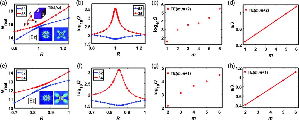
Figures 1(a) and 1(b) show and the -factor as a function of the size ratio for modes TE(3,5) and TE(5,3) which belong to type I. Interestingly, the -factor reaches its maximum value of 3300 at for TE(3,5) while the avoid-crossing occurs for in these two modes. Other high- modes fall within the category of type I, such as TE(1,3) and TE(2,4), can be found at the same critical ratio (see Fig. S2 in the Supplemental Materials). Figures 1(c) and 1(d) show the -factor and (or ) for mode while the value of increases from 1 to 5. The -factor can be up to for mode TE(5,7) while the resonant wavelength is still larger than the width of the square NW. Even higher -factors can be obtained for with . For instance, for , the -factor can get up to . The resonant wavelength, however, will become smaller than the width of the square NW. Thus, there is a balance between the high- and the dimensions of the structure. Another interesting point is that shows a linear dependence on . Such a linear relationship can be explained from the ray optics perspective (see Sec. S2 and Fig. S3 in the Supplemental Materials).14,28 It can help to facilitate the process of finding modes even with a higher -factor for large .

Figure 1.Properties of the high- modes in the single rectangular NW. (a), (b) Real part and -factor of the eigenvalue of modes TE(3,5) and TE(5,3) (type I) as functions of size ratio . (c), (d) -factor and as functions of for high- mode at the critical ratio. (e), (f) Real part and -factor of the eigenvalue of modes TE(3,4) and TE(5,2) versus the size ratio . (g), (h) -factor and , as functions of for high- mode at the critical ratio.
Following the same approach, many high- modes belonging to types II and III can be found. As an example of type II, Figs. 1(e) and 1(f) show the and -factor as a function of size ratio for a pair of modes TE(5,2) and TE(3,4). Different from the case of type I, the anticrossing feature appears at , and the factor for TE(3,4) reaches the maximum value of 1309, while it is 33 for mode TE(5,2). More type II high- modes are presented in Fig. S4 in the Supplemental Materials. Note that the critical ratio is always between 0 and 1 (see Fig. S5 in the Supplemental Materials). We also plot the -factor and for a high- mode TE as a function of . Similarly, the -factor increases sharply with and can reach the value of for the mode TE(6,7). We also found that is directly proportional to . Another example of the type II mode is shown in Fig. S6 in the Supplemental Materials. The type III case is similar to type II and, therefore, the relevant results are put in Fig. S7 in the Supplemental Materials. For the type IV, note that the complex eigenvalue of TE for the size ratio is the same as the eigenvalue for for the size ratio . Therefore, if type II or type III pair modes TE and TE(, ) display avoid-crossing features at the critical ratio and the -factor of has a maximum value, TE and will show avoided crossing at , and will have the largest -factor.
We confirm the existence of such high- modes at the critical size ratio by calculating the energy density mapping and scattering efficiency mapping versus both the size ratio and the normalized frequency . Here, the incident wave is TE polarization with the electric field along the axis. For some leaky modes such as TE(2,4) and TE(4,2), the eigenfield presents an antisymmetric distribution, and they cannot be excited by a normal incident wave. Therefore, the incident angle is set to 15 deg with respect to the axis to excite all of the eigenmodes. For a given size ratio, each peak in the energy density can be perfectly correlated to one of the leaky modes. From Fig. 2(a), an excellent agreement can be found between the resonant peaks in the mapping and the real part of the eigenvalue for pair modes TE(3,5) and TE(5,3). Furthermore, the line width of the resonant peak indeed becomes the narrowest at , which means that the -factor reaches the maximum value. The narrowing effect of linewidth can also be found in scattering spectrum mapping, as shown in Fig. 2(b). A similar phenomenon can also be applied to other pair modes TE(3,4) and TE(5,2) [Figs. 4(c) and 4(d)], TE(2,3) and TE(4,1) [Figs. S8(a) and S8(b) in the Supplemental Materials], TE(2,4) and TE(4,2) [Figs. S8(c) and S8(d) in the Supplemental Materials].
Figure 2.Total energy density and scattering efficiency for the rectangular NW with different size ratios. (a), (b) Logarithm total energy density and scattering efficiency mapping versus and . Two modes TE(3,5) and TE(5,3) are labeled as black and red circles. (c), (d) Logarithm of total energy density and scattering efficiency mapping versus and . Two modes TE(3,4) and TE(5,2) are labeled as black and red circles.
2.2 Physical Explanation of High-Q Mode by Multipole Decomposition
To get a better insight into radiative properties of the high- modes, we employ the multipole expansion.29–31 Here, we again consider the case of NW at oblique incidence () with TE polarization. Figure 3(a) shows scattering efficiency contributed by multipoles for a square NW. Two resonant peaks can be observed at and , which are related to the low- mode TE(5,3) and high- mode TE(3,5). The scattering efficiency around is dominated by a single multipole, electric quadrupole (), exhibiting a sharp Fano profile.32,33 In contrast, there are two dominant multipoles in the scattering efficiency for the low- mode around . This is also confirmed by the multipole analysis on the two eigenmodes TE(3,5) and TE(5,3). Indeed, from Fig. 3(b), there are two radiation channels ( and ) for mode TE(5,3), but only one dominant radiation channel () exists for mode TE(3,5). Each multipole can be considered as an independent channel for the radiating decay. Thus, coupling to more leaky channels with a larger radiation intensity will, in general, reduce the -factor. That is why it is expected that high- modes should couple to only one radiative channel with a small leakage, described by a single multipole.
Figure 3.Multipole analysis of the high- modes. (a) Multipolar contribution on the scattering cross section of the square NW under the excitation oblique incidence plane wave (). (b), (c) Multipole analysis and Fourier transformation on the eigenfields of two modes TE(3,5) and TE(5,3). (d), obtained from a Fourier transformation of eigenfields for two modes. (e) Multipolar contribution on scattering cross section of the rectangular NW with excited by the obliquely incident plane wave (). (f), (g) Multipole analysis and Fourier transformation on the eigenfields of two modes TE(3,4) and TE(5,2). (h) obtained from Fourier transformation of eigenfields for two modes. (i) Decomposition of TE(3,5) for the rectangular NW into and of eigenmodes for the circular NW. (j) Decomposition of TE(5,3) for the rectangular NW into and of eigenmodes for the circular NW.
Importantly, we can also find these radiation channels by carefully comparing its eigenfield distribution to the electric field distribution of the eigenmode for an infinite cylinder. For example, for mode TE(3,5), its eigenfield may be regarded as a superposition of eigenmodes and for the cylinder in Fig. 3(i), which serve as the orthogonal basis for the multipole expansion method. The radiation contribution of is much larger than that of from the field distribution. That also explains that dominates the radiation for TE(3,5). At the same time, the eigenfield of TE(5,3) may be viewed as the superposition of eigenmodes and for the cylinder, as shown in Fig. 3(j). Moreover, the radiation intensity for both channels in TE(3,5) is much lower than the counterparts in TE(5,3). From the perspective of the radiation channel, we may attribute the extreme confinement of TE(3,5) to the fact that these two leaky channels are more confined compared with leaky channels of TE(5,3). This explanation also works for the modes TE(3,4) and TE(5,2) belonging to the category of type II [see Figs. 3(e) and 3(f) and Fig. S9 in the Supplemental Materials]. Ideally, the eigenmode with the closest field profile to the eigenmode ( and ) in the cylinder will always have a high -factor because there is only one leaky channel with the minimum radiation intensity. The larger mode number is, the higher the -factor. This concept has been successfully applied to design the whisper gallery mode with an ultrahigh -factor.2 We also find a similar phenomenon in a relatively low-order mode. For example, mode TE(2,4) for NW with and TE(2,3) for NW with reach maximum values of 885 and 145, respectively. Multipole analysis of the eigenfield indicates that only one radiation channel exists for these two modes (see Fig. S10 in the Supplemental Materials). The major leaky channels for TE(2,3) and TE(2,4) are eigenmodes and of the cylinder, respectively (see Figs. S11(a) and S11(b) and Figs. S11(e) and S11(f) in the Supplemental Materials]. Both have better field confinement than eigenmode and eigenmode that are main radiation channel of modes TE(4,1) and TE(4,2), respectively [see Figs. S11(c) and S11(d) and Figs. S11(g) and S11(h) in the Supplemental Materials]. In fact, the suppressed electric dipole that is realized by an in-phase magnetic dipole and an electrical quadrupole34 is essential for building a magnetic mirror.
The radiative properties of an arbitrary source can also be analyzed in momentum space. It is known that only the nonzero current “on-the-shell” in -space contributes to the far-field radiation.35 Thus, it is instructive to analyze the electric field in momentum space of the high- mode at the critical ratio to get a more profound physical insight. To do this, we perform the Fourier transform on the eigenfield of the high- modes shown in Figs. 3(c) and 3(g). Here, it is worth pointing out that the electric field contributes to the outward radiation only when . Therefore, we extract on the white circle boundary and plot them in Figs. 3(d) and 3(h). Indeed, the radiation field of the high- mode has a much lower amplitude, and the radiation channel is narrower. For the resonant mode with an extremely high -factor, approaches zero at the circle boundary ().
2.3 High-Q Modes in Rectangular NW for TM Case
The above phenomenon can also be generalized to the rectangular NW with TM polarization. However, it is interesting that avoid-crossing is not always the prerequisite of realizing a high- mode in TM cases. For example, as shown in Figs. 4(a) and 4(b), mode TM(2,3) reaches the maximum -factor while crossing happens between pair modes TM(2,3) and TM(4,1). More crossing cases can be found for pair modes TM(3,3) and TM(5,1) in Figs. S12(a) and S12(b) in the Supplemental Materials, TM(4,4) and TM(6,2) in Figs. S12(c) and S12(d) in the Supplemental Materials. Figures 4(c) and 4(d) show the case of pair modes TM(3,4) and TM(5,2), where the high- mode happens at the avoided crossing. More avoided crossing cases can be found between modes and , such as TM(2,4) and TM(4,2) in Figs. 4(e) and 4(f), and TM(3,5) and TM(5,3) in Figs. S13(a) and S13(b) in the Supplemental Materials. It is entirely different from the cases of TE polarization, in which avoid-crossing is the necessary condition to realize the high- mode. Such a difference is also reflected in the mode evolutions (see Fig. S14 in the Supplemental Materials). For TE(2,3) and TE(4,1), the modes interchange with each other while the structure crosses the critical size ratio may suggest a relatively strong coupling between these two modes.36,37 Nevertheless, modes TM(2,3) and TM(4,1) remain similar field profiles, which may indicate a weak coupling between them (see Sec. S3, Table S2, and Fig. S15 in the Supplemental Materials). In addition, we also perform the multipole analysis on the eigenmode at different size ratios for both TE and TM cases. It can be found that the channel for both cases is reduced to a minimum at a critical size ratio (see Fig. S16 in the Supplemental Materials). Thus, the high- mode, on the other hand, can be regarded as an anapole state38,39 for which the radiation can be significantly quenched due to the total elimination of one leaky channel. In addition, -factor and versus for the high- mode , , and are calculated and shown in Fig. S17 in the Supplemental Materials. The -factor can be up to for mode TM(5,5) with (subwavelength scale). Moreover, similar to the TE case, almost linear dependence can be found between and . Also, we plot the critical size ratio versus for high- mode , , and , which can be found in Fig. S18 in the Supplemental Materials. The high- mode for the TM case is also well explained by multipole analysis on the eigenmode (see Fig. S19 in the Supplemental Materials). Importantly, these high- modes are not limited to the dielectric structure with the high refractive indices, such as for 4. Figure S20 in the Supplemental Materials shows the different high- modes of a rectangular NW as the refractive index varies from 2 to 8. One interesting thing is that the -factor does not always monotonically increase with the increasing refractive index. For example, the -factor for the high- mode TE(2,4) increases much faster than that of the high- mode TE(3,5), which becomes saturated for . Therefore, the refractive index-dependent -factor can help us to immediately find which mode should be chosen when a high- factor is desired for semiconductors with a different refractive index.
Figure 4.High- mode for the TM case. (a), (b) Real part and -factor of the eigenvalue for modes TM(2,3) and TM(4,1) as functions of the size ratio . (c), (d) Real part and -factor of the eigenvalue for modes TM(3,4) and TM(5,2) versus the size ratio .
2.4 High-Q Modes in a Single Nanoparticle
So far, we only discuss how to find the QBIC-induced high- mode in a single rectangular NW. The above approach can also be applied to a 3-D nonspherical structure, including the cuboid and cylinder with finite thickness. Here, we use a single cuboid as an example to demonstrate how to find a high- mode. For the sake of convenience and without loss of generality, and are assumed. Also, the mode number along is chosen as 1 for simplicity. We first consider magnetic eigenmodes (1,2,3) and (1,4,1) in the plane. Remarkably, from Figs. 5(a) and 5(b), a similar anticrossing feature can be observed for these two modes, and the -factor reaches a maximum of 325 at . The results of multipole analysis on the modes (1,4,1) and (1,2,3) indicate that the main radiation channels are and , and , respectively [see Fig. 6(a)]. Careful examination on the eigenfield distribution tells us that these two channels can be linked to eigenmodes and for sphere nanoparticles. obtained from a Fourier transform on the eigenfield has a much lower amplitude for (1,2,3) than that of mode (1,4,1) [see Fig. 6(b)]. It again confirms that the radiation is suppressed to a minimum. Another example of high- and low- modes, (1,4,2) and (1,2,4), are shown in Figs. 5(c) and 5(d). The -factor is up to . Different from the 2D NW case, a single cuboid can support both electric and magnetic eigenmodes. The conclusion drawn from magnetic modes can also be applied to electric modes. Following a similar approach, we find another two electric high- modes, (1,2,3) [see Figs. 5(e) and 5(f)] and (1,2,4) [see Figs. 5(g) and 5(h)]. However, these two are a little bit different. The mode features for (1,2,3) and (1,4,1) are crossing while anticrossing occurs for pair electric modes (1,4,2) and (1,2,4). Other high- modes in a single cuboid can be found in Fig. S21 in the Supplemental Materials. Besides, we want to point out that such a strategy also works for a cuboid with . Those high- modes can be constructed using a similar way. In fact, we can treat the single cuboid as a truncated rectangular NW. When the length of the axis becomes finite for the NW, we will expect the increase of -factor because there is confinement in the third dimension for the 3D cuboid compared to the NW, which is demonstrated in Fig. S22 in the Supplemental Materials. Last, another typical example of a single particle is a cylinder with finite thickness. We present two pairs of magnetic high- modes of a single disk in Fig. S23 in the Supplemental Materials. One is magnetic mode (1,2,3) and (1,4,1) while the other is magnetic mode (1,2,4) and (1,4,2). Similarly, electric high- modes, such as (1,2,3) and (1,2,4), can be found and shown in Fig. S24 in the Supplemental Materials. The design principles are the same, and we shall not repeat them here. Note that in Refs. 17 and 36, the modes (1,2,3) and (1,4,1) are also described as Mie mode and Fabry–Perot mode. However, not all pair high- and low- modes can be regarded as Mie mode and Fabry–Perot mode. For example, both modes (1,4,2) and (1,2,4) belong to Mie mode. A similar phenomenon can also be found in a single 2D rectangular NW. For example, pair modes TE(2,4) and TE(4,2), TE(3,4) and TE(5,2), TE(3,5) and TE(5,3), TM(2,4) and TM(4,2), TM(3,4) and TM(5,2), cannot be categorized into Mie mode and Fabry–Perot mode. Therefore, our strategy represents the perfect solution of finding all high- modes in a single dielectric nanocavity with a rectangular cross section.
Figure 5.High- mode for the single 3D nanoparticle. (a), (b) Real part and -factor of the eigenvalue for the magnetic eigenmode (1,2,3) and (1,4,1) in the single cuboid as functions of the size ratio while . (c), (d) Real part and -factor of the eigenvalue for the magnetic eigenmode (1,2,4) and (1,4,2) as functions of the size ratio of a cuboid. (e), (f) Real part and -factor of the eigenvalue for the electric eigenmode (1,2,3) and (1,4,1) as functions of the size ratio of the cuboid. (g), (h) Real part and -factor of the eigenvalue for the electric eigenmode (1,2,4) and (1,4,2) as functions of the size ratio of a cuboid.
Figure 6.(a) Multipole analysis on the eigenfields for two modes of the cuboid, (1,4,1) and (1,2,3). (b) distribution for two modes.
3 Experimental Verification of High-Q Mode in Single Si NW
We move to experimentally demonstrate the high- factor by exploring the scattering characteristics of a single rectangular silicon NW on a quartz substrate. Mode TE(3,4) is used to realize the high- mode at 1390 nm. The length of Si NW is in real fabrication to mimic the behavior of NW (see Fig. S22 in the Supplemental Materials). The fabrication of a series of NWs with different widths is described as follows. First, the amorphous silicon thin film with a thickness of 825 nm is deposited on glass substrate with plasma-enhanced chemical vapor deposition (Oxford PlasmaLab System 100). Subsequently, positive electroresist was spin-coated over the film. We then exposed the resist by applying electron-beam lithography (Raith 150) and developed. A 50-nm Cr film was evaporated onto the sample, followed by the lift-off process to generate Cr masks. Using reactive ion etching processes, Cr rectangles were transferred to the silicon film. The residual Cr disks were further removed by wet Cr etching. The scatterings of the fabricated sample were measured using a home-built white-light spectroscopy setup in a confocal configuration, as shown in Fig. 7. The sample was backside illuminated by a white-light source (fiber-coupled tungsten halogen light bulb). A polarizer is put between the focal lens and light source to control the linear polarization of the incidence wave. Using a objective and a diaphragm, the light transmitted through the sample in the normal direction was then collected and directed to the spectrometer (Princeton Instruments Acton SP 2300 monochromator with Andor DU490A-1.7 InGaAs array detector). Considering there is no absorption from the fabricated silicon material in the NIR range, the scattering cross sections were then estimated using the approximate relation , where is the measured transmission (normalized to the transmission of the substrate when no NW is presented) in the normal direction.
Figure 7.Schematic drawing of measurement system.
Figure 8(a) shows the schematic drawing of the dielectric NW on quartz substrate, while Figs. 8(b) and 8(c) show the measured and simulated scattering spectrum of a single NW with different size ratios. The structure is illuminated by an incidence wave with a TE polarization (the electric field is parallel to the infinite axis of the NW). Good agreement can be found between numerical calculation based on the FEM method and experimental results. The resonant frequency and -factor are extracted by the standard Fano fitting procedure (see Sec. 4 and Figs. S25 and S26 in the Supplemental Materials).22 It can be also found that the resonant frequency shows avoided crossing at , around which the -factor reaches a maximum value of 211. A slight shift of the critical size ratio may be attributed to the imperfect vertical sidewall of the NW. The measured -factor is lower than the theoretical prediction because of the presence of glass substrate, which reduces the index contrast and causes more leakage into the substrate. Also, the refractive index of Si here is 3.36, lower than the value of we used in the previous discussion. These two combined effects make the measured -factor reduce six times compared with the theoretical prediction shown in Fig. 1(f). Note that the -factor can be further improved to about 746 by suspending the NW, which can be realized by wet etching underneath using HF acid. We also demonstrate that the -factor for the mode TE(3,5) can reach 380 for a silicon NW on quartz substrate with the thickness being 1130 nm (see Fig. S27 in the Supplemental Materials) while the -factor can be up to 294 for TM(3,5) (see Fig. S28 in the Supplemental Materials). Here, we want to point out that the measured -factor is comparable to that of QBIC in Refs. 40–42. The higher -factor can be realized with high-order QBIC in a single cuboid or disk, such as (1,2,4). Also, the -factor can be further improved by putting a dielectric cuboid or disk on epsilon near zero substrate or putting a mirror around the cuboid or disk.41,42
Figure 8.Experimental verification of high-Q mode in the single silicon NW on quartz. (a) Schematic drawing of the single Si NW on a quartz substrate under normal incidence for TE polarization. (b) Experimentally measured scattering spectrum for the single NW with and . Top inset is the eigenfield distribution of mode TE(3,4) while the bottom inset is an SEM image of fabricated Si NW (the bar in the inset is 500 nm). (c) Simulation and measured scattering spectra for the single NW with different widths while the thickness of the NW is fixed as 825 nm. High- modes are indicated with arrows. (d) Extracted -factor and (e) for pair modes TE(3,4) and TE(5,2) as a function of the size ratio.
4 Conclusion
We developed a robust approach to explore high- super-cavity modes in a single dielectric structure with a rectangular cross section, which includes a 2D rectangular NW, 3D disk, and cuboids. Such supercavity modes, also called as a quasi bound-state-in-the-continuum, are found by constructing the avoid-crossing or crossing for pair leaky modes (high- and low- modes). The -factor of TE(5,7) can be up to even for a square NW with . The strong confinement of the electric field for these supercavity modes can be explained as the suppression of the radiation in limited leaky channels or radiation quenching to a minimum in the momentum space. We also experimentally confirm this type of high- mode in a single Si subwavelength NW. Our findings provide a general guiding principle to design an extreme high- mode with a relatively small material volume and will find applications in lasing,40,43 enhanced nonlinear harmonic generation,41,44,45 and strong coupling.
References
[1] Y. Akahane et al. High-Q photonic nanocavity in a two-dimensional photonic crystal. Nature, 425, 944-947(2003).
[2] K. J. Vahala. Optical microcavities. Nature, 424, 839-846(2003).
[3] C. W. Hsu et al. Observation of trapped light within the radiation continuum. Nature, 499, 188-191(2013).
[4] C. W. Hsu et al. Bound states in the continuum. Nat. Rev. Mater., 1, 16048(2016).
[5] A. Kodigala et al. Lasing action from photonic bound states in continuum. Nature, 541, 196-199(2017).
[6] S. T. Ha et al. Directional lasing in resonant semiconductor nanoantenna arrays. Nat. Nanotechnol., 13, 1042-1047(2018).
[7] Z. Liu et al. High-Q quasibound states in the continuum for nonlinear metasurfaces. Phys. Rev. Lett., 123, 253901(2017).
[8] Q. Song et al. Near-IR subwavelength microdisk lasers. Appl. Phys. Lett., 94, 061109(2009).
[9] P. E. Landreman et al. Fabry–Perot description for Mie resonances of rectangular dielectric nanowire optical resonators. Opt. Express, 24, 29760-29772(2016).
[10] D. J. Traviss et al. Antenna resonances in low aspect ratio semiconductor nanowires. Opt. Express, 23, 22771-22787(2015).
[11] L. Huang, Y. Yu, L. Cao. General modal properties of optical resonances in subwavelength nonspherical dielectric structures. Nano Lett., 13, 3559-3565(2013).
[12] A. I. Kuznetsov et al. Optically resonant dielectric nanostructures. Science., 354, aag2472(2016).
[13] Y. S. Kivshar, A. E. Miroshnichenko. Meta-optics with Mie resonances. Opt. Photonic News, 28, 24-31(2017).
[14] J. Wiersig. Formation of long-lived, scarlike modes near avoided resonance crossings in optical microcavities. Phys. Rev. Lett., 97, 253901(2006).
[15] Q. H. Song, H. Cao. Improving optical confinement in nanostructures via external mode coupling. Phys. Rev. Lett., 105, 053902(2010).
[16] H. Cao, J. Wiersig. Dielectric microcavities: model systems for wave chaos and non-Hermitian physics. Rev. Mod. Phys., 87, 61-111(2015).
[17] M. V. Rybin et al. High-Q supercavity modes in subwavelength dielectric resonators. Phys. Rev. Lett., 119, 243901(2017).
[18] W. Chen, Y. Chen, W. Liu. Multipolar conversion induced subwavelength high-Q Kerker supermodes with unidirectional radiations. Laser Photonics Rev., 13, 1900067(2019).
[19] S. Gladyshev, K. Frizyuk, A. Bogdanov. Symmetry analysis and multipole classification of eigenmodes in electromagnetic resonators for engineering their optical properties. Phys. Rev. B, 102, 075103(2020).
[20] I. Volkovskava et al. Multipolar second-harmonic generation from high-Q quasi-BIC states in subwavelength resonators. Nanophotonics, 9, 3953-3963(2020).
[21] M. Odit et al. Observation of supercavity modes in subwavelength dielectric resonators. Adv. Mater.(2020).
[22] H. Friedrich, D. Wintgen. Interfering resonances and bound states in the continuum. Phys. Rev. A, 32, 3231-3242(1985).
[23] A. F. Sadreev, E. N. Bulgakov, I. Rotter. Bound states in the continuum in open quantum billiards with a variable shape. Phys. Rev. B, 73, 235342(2006).
[24] K. N. Pichugin, A. F. Sadreev. Interaction between coaxial dielectric disks enhances the Q factor. J. Appl. Phys., 126, 093105(2019).
[25] A. A. Lyapina et al. Bound states in the continuum in open acoustic resonators. J. Fluid. Mech., 780, 370-387(2015).
[26] Y. Yu, L. Cao. Coupled leaky mode theory for light absorption in 2D, 1D, and 0D semiconductor nanostructures. Opt. Express, 20, 13847-13856(2012).
[27] L. Cao et al. Engineering light absorption in semiconductor nanowire devices. Nat. Mater., 8, 643-647(2009).
[28] J. Wiersig. Hexagonal dielectric resonators and microcrystal lasers. Phys. Rev. A., 67, 023807(2003).
[29] S. Q. Li, K. B. Crozier. Origin of the anapole condition as revealed by a simple expansion beyond the toroidal multipole. Phys. Rev. B, 97, 245423(2018).
[30] P. Grahn, A. Shevchenko, M. Kaivola. Electromagnetic multipole theory for optical nanomaterials. New J. Phys., 14, 093033(2012).
[31] W. Chen, Y. Chen, W. Liu. Singularities and Poincaré indices of electromagnetic multipoles. Phys. Rev. Lett., 122, 153907(2019).
[32] A. E. Miroshnichenko, S. Flach, Y. S. Kivshar. Fano resonances in nanoscale structures. Rev. Mod. Phys., 82, 2257-2298(2010).
[33] M. I. Tribelsky, A. E. Miroshnichenko. Giant in-particle field concentration and Fano resonances at light scattering by high-refractive index particles. Phys. Rev. A, 93, 053837(2016).
[34] A. K. Gonzalez-Alcalde et al. Magnetic mirror metasurface based on the in-phase excitation of magnetic dipole andelectric quadrupole resonances. J. Appl. Phys., 125, 243103(2019).
[35] K. Kim, E. Wolf. Non-radiating monochromatic sources and their fields. Opt. Commun., 59, 1-6(1986).
[36] A. A. Bogdanov et al. Bound states in the continuum and Fano resonances in the strong mode coupling regime. Adv. Photonics, 1, 016001(2019).
[37] L. Zhang et al. Photonic-crystal exciton-polaritons in monolayer semiconductors. Nat. Commun., 9, 713(2018).
[38] A. E. Miroshnichenko et al. Nonradiating anapole modes in dielectric nanoparticles. Nat. Commun., 6, 8069(2015).
[39] L. Xu et al. Boosting third-harmonic generation by a mirror-enhanced anapole resonator. Light. Sci. Appl., 7, 44(2018).
[40] V. Mylnikov et al. Lasing action in single subwavelength particles supporting supercavity modes. ACS Nano, 14, 7338-7346(2020).
[41] K. Koshelev et al. Subwavelength dielectric resonators for nonlinear nanophotonics. Science, 367, 288-292(2020).
[42] M. P. Nezhad et al. Room-temperature subwavelength metallo-dielectric lasers. Nat. Photonics, 4, 395-399(2010).
[43] C. Huang et al. Ultrafast control of vortex microlasers. Science, 367, 1018-1021(2020).
[44] L. Carletti et al. Giant nonlinear response at the nanoscale driven by bound states in the continuum. Phys. Rev. Lett., 121, 033903(2018).
[45] L. Xu et al. Dynamic nonlinear image tuning through magnetic dipole quasi-BIC ultrathin resonators. Adv. Sci., 6, 1802119(2019).