
Xinyuan Fang, Haocheng Yang, Wenzhe Yao, Tianxin Wang, Yong Zhang, Min Gu, Min Xiao, "High-dimensional orbital angular momentum multiplexing nonlinear holography," Adv. Photon. 3, 015001 (2021)
- Advanced Photonics
- Vol. 3, Issue 1, 015001 (2021)
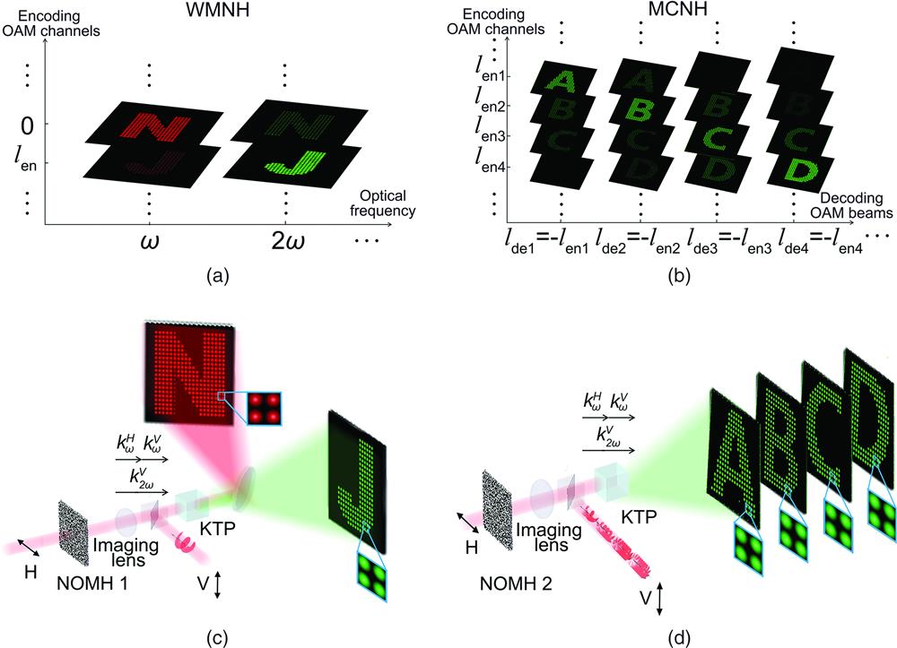
Fig. 1. Principle of OMNH and its applications in type-II SHG. (a), (b) Concepts of (a) WMNH and (b) MCNH. (c) Schematic diagram of NOMH1 capable of independently reconstructing pattern N in FW and pattern J in SHW based on WMNH in a type-II SHG process. (d) Schematic diagram of NOMH2 capable of reconstructing patterns A, B, C, and D in SHW based on MCNH in a type-II SHG process.
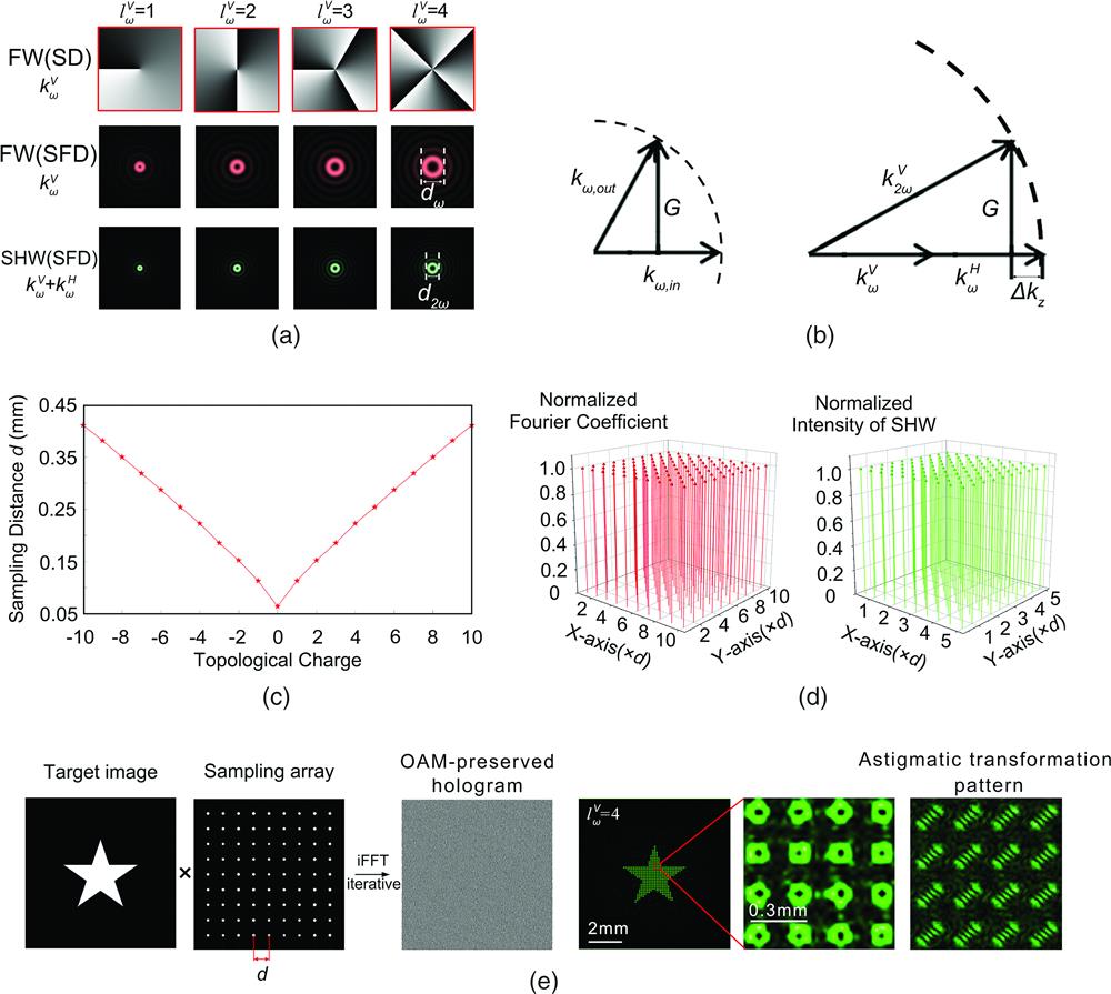
Fig. 2. Designing principle of OAM-preserved hologram in OMNH. (a) The FW sampling distance (Supplemental Materials for details). (e) Under the scheme in Fig. 1(c) , we numerically design an OAM-preserved hologram for a star (left) and calculate the reconstructed SH image (right). The FW OAM beam carries a topological charge of
Fig. 3. Experimental demonstration of NOMH for WMNH. (a) Experimental setup for reconstructing FW and SHW images. LP, linear polarizer; SLM1/SLM2, spatial light modulator; L1-L5, lens; BS, beam splitter; PBS, polarization beam splitter; HWP, half-wave plate; DM, dichroic mirror. (b) FW (left) and SHW (right) images reconstructed by a decoding FW OAM beam with
Fig. 4. Demonstrations of OAM- and polarization-dependent MCNH in SHW. (a) The images in the SHW channels are reconstructed by the vertically polarized decoding FW with


Set citation alerts for the article
Please enter your email address

© Copyright 2018-2021 | Chinese Laser Press. All Rights Reserved 沪ICP备15018463号-20