1Nanjing University, College of Engineering and Applied Sciences, School of Physics, National Laboratory of Solid State Microstructures, Nanjing, China
2University of Shanghai for Science and Technology, School of Optical-Electrical and Computer Engineering, Centre for Artificial-Intelligence Nanophotonics, Shanghai, China
3University of Arkansas, Department of Physics, Fayetteville, Arkansas, United States
Nonlinear holography has been identified as a vital platform for optical multiplexing holography because of the appearance of new optical frequencies. However, due to nonlinear wave coupling in nonlinear optical processes, the nonlinear harmonic field is coupled with the input field, laying a fundamental barrier to independent control of the interacting fields for holography. We propose and experimentally demonstrate high-dimensional orbital angular momentum (OAM) multiplexing nonlinear holography to overcome this problem. By dividing the wavefront of the fundamental wave into different orthogonal OAM channels, multiple OAM and polarization-dependent holographic images in both the fundamental wave and second-harmonic wave have been reconstructed independently in the spatial frequency domain through a type-II second harmonic generation process. Moreover, this method can be easily extended to cascaded χ2 nonlinear optical processes for multiplexing in more wavelength channels, leading to potential applications in multicasting in optical communications, multiwavelength display, multidimensional optical storage, anticounterfeiting, and optical encryption.
Holography involves using a hologram to reconstruct both the intensity and phase information of an object.1 Since its invention, it has been widely applied to three-dimensional holographic display,2 data storage,3 optical encryption,4 holographic interferometry,5 and microscopy.6 Inspired by the unprecedented demand for information processing, different orthogonal physical dimensions of light, including wavelength,7 polarization,8 space,9 and time,4 have been exploited for multiplexing multiple parallel information channels in a single hologram, which is called optical multiplexing holography.
Recently, to shape the wavefront of the light generated in a nonlinear optical process, the holographic technique has been extended from the linear optical region to nonlinear optics.10–15 While information channels intrinsically increase with the appearance of new optical frequencies in the nonlinear frequency conversion processes, all of the interacting electrical fields are coupled to each other according to the nonlinear wave-mixing equations,16 leading to severe inconvenience in simultaneously utilizing different optical frequency components [see Fig. S1(a) in the Supplemental Materials]. By making using of the advanced GS algorithm and unique characteristics of nonlinear coupling in a specially designed nonlinear metasurface, spin angular momentum has been introduced to modulate the intensity of a holographic field encoded in different optical frequencies.17–19 However, it is still a great challenge to construct a universal method that is suitable for other popular nonlinear materials including (KTP) and crystals. In particular, nonlinear coupling (especially in the phase information) seriously impedes advanced applications in nonlinear holography. For example, in high-dimensional nonlinear holographic display, it is almost impossible to distinguish multiple holographic patterns encoded in each wavelength under the restriction of nonlinear coupling [see Fig. S1(b) in the Supplemental Materials].
In the last decade, orbital angular momentum (OAM), due to its inherent orthogonality,20 has emerged as a new degree of freedom of light for boosting classic21–23 and quantum information capacity.24–26 Very recently, we have experimentally demonstrated linear OAM holography in the spatial frequency domain (SFD).27,28 Here, we propose and experimentally demonstrate the use of OAM as an information carrier in nonlinear holography, i.e., achieving OAM multiplexing nonlinear holography (OMNH), to completely bypass the fundamental limitation due to nonlinear wave coupling. In comparison to previous works, our method has several exceptional advantages. First, the nonlinear interacting fields are controlled independently, which enables us to facilitate wavelength-multiplexing nonlinear holography (WMNH). Second, OAM can be further utilized to encode multiple patterns for each wavelength to increase information channel numbers, resulting in unprecedented multichannel nonlinear holography (MCNH). In addition, our method is suitable for various nonlinear crystals. Considering that the introduction of OAM does not change the conventional phase matching condition,29 one can achieve high conversion efficiency through a proper phase matching configuration.
Sign up for Advanced Photonics TOC. Get the latest issue of Advanced Photonics delivered right to you!Sign up now
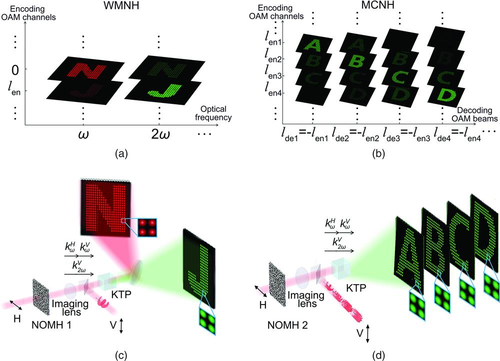
Figure 1 shows the two layers of OAM multiplexing nonlinear holography, i.e., WMNH and MCNH. As shown in Fig. 1(a), the concept of WMNH is illustrated through second harmonic generation (SHG). The SFD of the hologram is expanded into two dimensions, i.e., optical frequency and OAM. In nonlinear optical processes, the interactions between fundamental beams () lead to second-harmonic (SH) frequency channel (). Distinctive images (letter N and letter J) in these optical frequency channels are distributed in different OAM spaces (0, ), leading to a nonlinear OAM-multiplexing hologram (NOMH) (carried by one fundamental beam). When a decoding OAM beam with an opposite helical phase (, ) interacts with the hologram-carrying beam, only the targeted image will appear in the designed optical frequency channel. Moreover, each optical frequency channel can be further divided into multiple sub-OAM spaces (), giving rise to the concept of MCNH. Figure 1(b) shows an example of MCNH at the optical frequency channel of . Individual images at can be reconstructed selectively using an OAM fundamental beam with the topological charge of , respectively. Note that MCNH can be implemented in all of the optical frequency channels.
Figure 1.Principle of OMNH and its applications in type-II SHG. (a), (b) Concepts of (a) WMNH and (b) MCNH. (c) Schematic diagram of NOMH1 capable of independently reconstructing pattern N in FW and pattern J in SHW based on WMNH in a type-II SHG process. (d) Schematic diagram of NOMH2 capable of reconstructing patterns A, B, C, and D in SHW based on MCNH in a type-II SHG process.
We demonstrate the principle of OAM multiplexing nonlinear holography through a type-II birefringence phase matching (BPM) SHG process in a KTP crystal [Figs. 1(c) and 1(d)]. There are two incident fundamental beams defined by and (with and representing horizontal and vertical polarizations, respectively). The output is a vertically polarized SH beam . Based on the nonlinear three-wave mixing equation, the SH electrical field is given by . Here, and represent the electrical fields of the second-harmonic wave (SHW) and fundamental wave (FW), respectively. is a constant that is proportional to the nonlinear coefficient of the crystal. When the BPM condition () is satisfied, one can achieve highly efficient SHG (see Fig. S2 in the Supplemental Materials).
The conceptual illustration of WMNH in type-II SHG is shown in Fig. 1(c). The goal of WMNH is to produce a letter N in FW and a letter J in SHW. The complex superposition of the holograms of N and J results in NOMH1. One FW () is shaped by NOMH1 and imaged into the nonlinear crystal. The other FW () carries the decoding OAM information (i.e., ). In the nonlinear frequency conversion process, the interaction between these two FW beams ( and ) leads to an SH frequency channel, which includes the inverse transformation of the FW as well as the transformation to the desired SHG mode. Specifically, considering the OAM conservation law,29,30 only when , each pixel of the letters N and J in the Fourier plane can be reconstructed as a Gaussian-mode solid spot at FW and SHW, respectively. Clearly, by use of the orthogonality of OAM modes, one can realize the desired WMNH without the limitation due to nonlinear coupling (see Note S1 in the Supplemental Materials).
The modeled illustration of MCNH at SHW is shown in Fig. 1(d). The FW () is imprinted with an NOMH2, in which the holograms of distinctive patterns (A, B, C, and D) are encoded with helical phases of , , , and , respectively. Only a given incident fundamental OAM beam with a special inverse helical phase (, , , ) can convert each pixel of the corresponding holographic SH image into a Gaussian-mode spot through a type-II SHG process in the KTP crystal.
2.1 Design of OAM-Preserved Hologram
To achieve high-dimensional OAM nonlinear holography, the orthogonality of OAM modes must be utilized in our method. Therefore, it is important to preserve the spiral phase in each pixel of the holographic image in the Fourier plane, leading to the concept of an OAM-preserved hologram.
First, it is critical to determine the sampling distance in the design. Considering the OAM conservation in the SHG process, one can calculate the minimal sampling distance ( and for FW and SHW, respectively) directly from the spatial frequency of the corresponding FW and SHW OAM beams [see Fig. 2(a), Fig. S3 and Note S2 in the Supplemental Materials).
Figure 2.Designing principle of OAM-preserved hologram in OMNH. (a) The FW sampling distance () and SHW sampling distance () calculated from spatial frequencies of the corresponding OAM beams in SFD. (b) The linear (left) and nonlinear (right) Raman–Nath processes in -space. Note that is significantly enlarged for clarity. The actual reciprocal vector is two-orders of magnitude less than the wave vectors in our experiment. (c) The dependence of the sampling distance for OAM-preserved hologram in OMNH on the topological charge of the FW OAM beam. (d) Taking into account , we calculate the normalized SH intensity distribution (right) reconstructed from a hologram with uniform Fourier coefficients (left). Clearly, the uniform SH intensity indicates a negligible influence from (see Note S4 in the Supplemental Materials for details). (e) Under the scheme in Fig. 1(c), we numerically design an OAM-preserved hologram for a star (left) and calculate the reconstructed SH image (right). The FW OAM beam carries a topological charge of . The intensity profile of each pixel presents a donut shape. The corresponding astigmatic transformation pattern of each pixel well proves the OAM preservation.
From the view point of -space, the sampling array utilized in the design of the OAM-preserved hologram produces a reciprocal vector () on the carrier FW (). Under a small diffraction angle, such a -induced spatial frequency shift for linear Raman–Nath diffraction of FW is about twice the value for nonlinear Raman–Nath diffraction of SHW [see Fig. 2(b), Note S3 in the Supplemental Materials]. Therefore, to maintain the OAM modes in both FW and SHW, the sampling constant should satisfy
Figure 2(c) shows the calculated dependence of sampling distance on the FW OAM order.
It should be noted that the diffraction angle of a designed hologram in our scheme is within the acceptance angle of BPM to guarantee high conversion efficiency of the nonlinear OAM-multiplexing holography. This can also be understood from the viewpoint of nonlinear Raman–Nath diffraction. The reciprocal vector introduces a certain phase mismatch along the propagation direction, i.e., , as shown in Fig. 2(b). According to the expression of SH conversion efficiency in nonlinear Raman–Nath diffraction ,31 the SH power varies with (caused by ). However, considering that the typical sampling distance is in our experiment, the value of is two orders of magnitude smaller than the wave vector. Therefore, the -induced phase mismatch can be ignored in our experiment. The uniform intensity distribution of SH image [Fig. 2(d)] also indicates a negligible influence of on the conversion efficiency (see Note S4 in the Supplemental Materials for details).
To design an OAM-preserved hologram, the target image is multiplied by a sampling array with the sampling constant . As shown in Fig. 2(c), is dependent on the maximal topological charge of the used FW OAM beam. Through the iterative iFFT algorithm, a phase-only OAM-preserved hologram is achieved [left panel in Fig. 2(e)]. Under the schemes shown in Fig. 1(c), we numerically calculate the reconstructed SHW patterns from an OAM-preserved hologram in the Fourier plane [right panel in Fig. 2(e)]. The reconstructing OAM beam carries a topological charge of . To determine the OAM states in each pixel, astigmatic transformation patterns are generated using a tilt lens,32 which well proves the preserved OAM information.
2.2 Experimental Results of OAM-Multiplexing Nonlinear Holography
Figure 3(a) shows the experimental setup to demonstrate OAM multiplexing nonlinear holography (see Sec. 2). A KTP crystal is used to fulfil the BPM requirements at the fundamental wavelength of 1064 nm. In the optical setup, the fundamental Gaussian wave is derived from a 1064-nm near-infrared laser with a repetition frequency of 20 kHz and a pulse width of 100 ns. After passing through a linear polarizer (LP), the horizontally polarized light is separated by a 50:50 nonpolarizing beam splitter (BS). In order to protect the spatial light modulator (SLM), the FW average power density of each path cannot exceed . The light in Path 1 is incident on SLM 1 (Holoeye Pluto-2-NIR-011), which displays the NOMH. Afterward, a optical system consisting of two lenses ( and ) is used to transfer the hologram onto an 8-mm-long KTP crystal, which is cut for type-II phase matching. Notably, an iris is put at the focal point of the L1, filtering out the unmodulated zeroth-order diffraction. In Path 2, the spiral phase (i.e., the decoding hologram) is loaded onto SLM 2 (Holoeye Pluto-2-NIR-011), and another system consisting of L3 and L4 ( and ) is used to reshape the incident decoding OAM FW. Here, a half-wave plate (HWP) with its fast axis oriented at 45° is used to rotate the polarization to a vertical one. After combination via a polarization beam splitter (PBS), the two FWs with different polarization directions propagate collinearly to participate in the type-II SHG. The subsequent broadband lens L5 () is used to perform the Fourier transform of the SHW and horizontally polarized FW. A dichroic mirror is used to separate the two wavelength channels, and the images are recorded by a CCD camera (Basler, acA2040-90uc).
Figure 3.Experimental demonstration of NOMH for WMNH. (a) Experimental setup for reconstructing FW and SHW images. LP, linear polarizer; SLM1/SLM2, spatial light modulator; L1-L5, lens; BS, beam splitter; PBS, polarization beam splitter; HWP, half-wave plate; DM, dichroic mirror. (b) FW (left) and SHW (right) images reconstructed by a decoding FW OAM beam with . (c) The intensity distribution of all the pixels in (b). The image pixels are numbered according to top-to-bottom and left-to-right sequences.
The procedure to build an NOMH for WMNH is introduced below. Two OAM-preserved holograms are encoded with (letter N) and (letter J), respectively. In this case, the sampling distance is decided by . After complex superposition of these two holograms, we use the phase term to compose the NOMH. Note that the use of phase-only NOMH has limited effects on the quality of nonlinear holographic images in our experiment (see Note S5 in the Supplemental Materials). In addition, to avoid the influence from the unmodulated zeroth order (see Fig. S4 in the Supplemental Materials), an additional blazed grating is superposed on the NOMH. Here, we design OAM-preserved holograms of letters N and J and encode them with different helical phases (i.e., for N, and for J). In this case, two wavelength channels (FW and SHW) and two OAM channels ( and 4) result in four information channels.
The experimental results of WMNH in the Fourier space are shown in Fig. 3(b). The pattern N, consisting of pixels of Gaussian-mode distribution, is well reconstructed in the FW. The crosstalk from the pattern J (featuring OAM pixels) is too weak to be clearly observed. When the decoding OAM FW beam () with a topological charge of [implemented by SLM 2 in Fig. 3(a)] participates in the type-II SHG, each pixel of letter J in the SHW channel is converted into a Gaussian mode spot. Here, the crosstalk mainly results from the OAM pixels of pattern N. In our experiment, the crosstalk has been further filtered out by a mask of hole arrays in each wavelength channel. Notably, because the target images (N and J) in our experiment are binary, the reconstructive images should have the uniform intensity distribution in theory. As shown in Fig. 3(c), the intensities of all the pixels have been analyzed. The slight intensity fluctuation can be attributed to the negligible modal crosstalk between the FW and SHW. To illustrate the whole process more clearly, a flow chart is given in Fig. S5 in the Supplemental Materials. In our experiment, the SHG conversion efficiency of nonlinear OAM-multiplexing holography is , which is enhanced by several orders of magnitude in comparison to previous works.33
Next, we experimentally demonstrate MCNH at SHW, in which multiple SH images can be selectively reconstructed. The experimental setup is the same as in Fig. 3(a). The designed NOMH includes the OAM-preserved holograms for patterns A, B, C, and D that are encoded with OAM subspaces of , , , , respectively (see Fig. S6 in the Supplemental Materials). Here, the sampling distance is decided by . Particularly, two wavelength channels and four OAM channels produce eight information channels. In the experiment, the NOMH is imprinted in one FW (), which carried both the FW and SHW target information. To obtain the information in the SH channel, the type-II KTP crystal and another decoding OAM FW are required. Only when inputting a vertically polarized decoding FW () with , 4, 6, 8, respectively, the corresponding SH images with Gaussian-mode pixels (patterns A, B, C, and D) can be separately reconstructed [Fig. 4(a)]. To analyze the crosstalk among the patterns encoded in different OAM channels, we also measure the intensity of each pixel. The intensity distributions of the reconstructive images in Fig. 4(b) have larger variations than those in Fig. 3(c). This can be attributed to two reasons. First, when using a larger OAM channel number (two in Fig. 3 and four in Fig. 4) and a smaller topological charge difference between the neighboring channels (four in Fig. 3 and two in Fig. 4), one can expect a larger crosstalk.27 Second, the sampling distance in Fig. 4 is larger than that in Fig. 3. Along with the grating function, they will lead to a larger phase mismatch along the propagation direction and therefore a lower SH conversion efficiency for the image pixels at the edge.
Figure 4.Demonstrations of OAM- and polarization-dependent MCNH in SHW. (a) The images in the SHW channels are reconstructed by the vertically polarized decoding FW with , 4, 6, 8, respectively (top). (b) The intensities of all of the pixels in four channels are analyzed. The image pixels are numbered according to top-to-bottom and left-to-right sequences.
Besides, MCNH can also be applied in the FW channel. In the decoding process, only a helical phase is needed to achieve the information on the FW channel. The experimental setup is shown in Fig. S7(a) in the Supplemental Materials. In this case, the NOMH is the same one used for MCNH at SHW. Only decoding OAM beams with horizontal polarization can be modulated by the SLM, leading to the reconstructions of corresponding FW images when , 4, 6, 8, respectively (see Fig. S7 in the Supplemental Materials). For decoding FW beams with vertical polarization, the FW patterns are switched off. Notably, because of the BPM requirements in the type-II SHG process, the SH patterns can be switched on and off for a vertically and horizontally polarized decoding FW, respectively [Fig. 4(a)]. As such, multiple individual output states in both FW and SHW can be feasibly reconstructed according to different input states.
3 Conclusions
Based on the OAM orthogonality in the Fourier plane, we have conceptually proposed the OAM-multiplexing nonlinear holography and experimentally demonstrated independent control of FW and SHW through OAM division of fundamental fields. Moreover, this method can be further extended to high harmonic generations if the phase-matching conditions are met simultaneously, leading to the exploitation of more wavelength channels. A cascaded type-II third-harmonic generation process has been modeled in Fig. S8 in the Supplemental Materials, in which three optical frequency channels can be prepared by dividing an object image (of a flower) into three individual parts [see Fig. S8(a) in the Supplemental Materials]. These three parts have also been encoded into three orthogonal OAM orders of , , , leading to the NOMH loaded on FW with horizontal linear polarization.34 As such, three distinctive images in the FW, SHW, and third-harmonic wave can be reconstructed simultaneously by an incident decoding OAM beam () with vertical linear polarization [see Note S6 and Fig. S8(b) in the Supplemental Materials].
The quality of the reconstructed holographic images can be further improved. For example, the image resolution can be enhanced using high-resolution NOMHs (such as in metasurface devices35) (see Note S7 and Fig. S9 in the Supplemental Materials). The SHG conversion efficiency is currently limited by the damage threshold of the SLM used in our experiment. The recently developed three-dimensional nonlinear photonic crystal36–38 provides yet another alternative platform to realize OAM-multiplexing nonlinear holography with higher-efficiency.
In conclusion, high-dimensional OAM multiplexing nonlinear holography can be implanted in most nonlinear optical platforms including the popular nanophotonic devices and nonlinear photonics crystals. Our experimental demonstration paves the way for its exciting applications in multiwavelength multicasting in optical communication (see Fig. S10 in the Supplemental Materials), multidimensional optical storage, anticounterfeiting, ultrahigh-security optical encryption, and all-optical multicolor diffractive neuron networks.39