
Ya Huang, Fengpu Wang, Xinnan Li, Zhe Chen, Bo Li, Chen Xu, Ting Cao. Large Aperture Off-Axis Aspherical Segment Test Using Refraction and Diffraction Mixed Compensation Based on Computer Generated Hologram[J]. Acta Optica Sinica, 2022, 42(12): 1212004
- Acta Optica Sinica
- Vol. 42, Issue 12, 1212004 (2022)
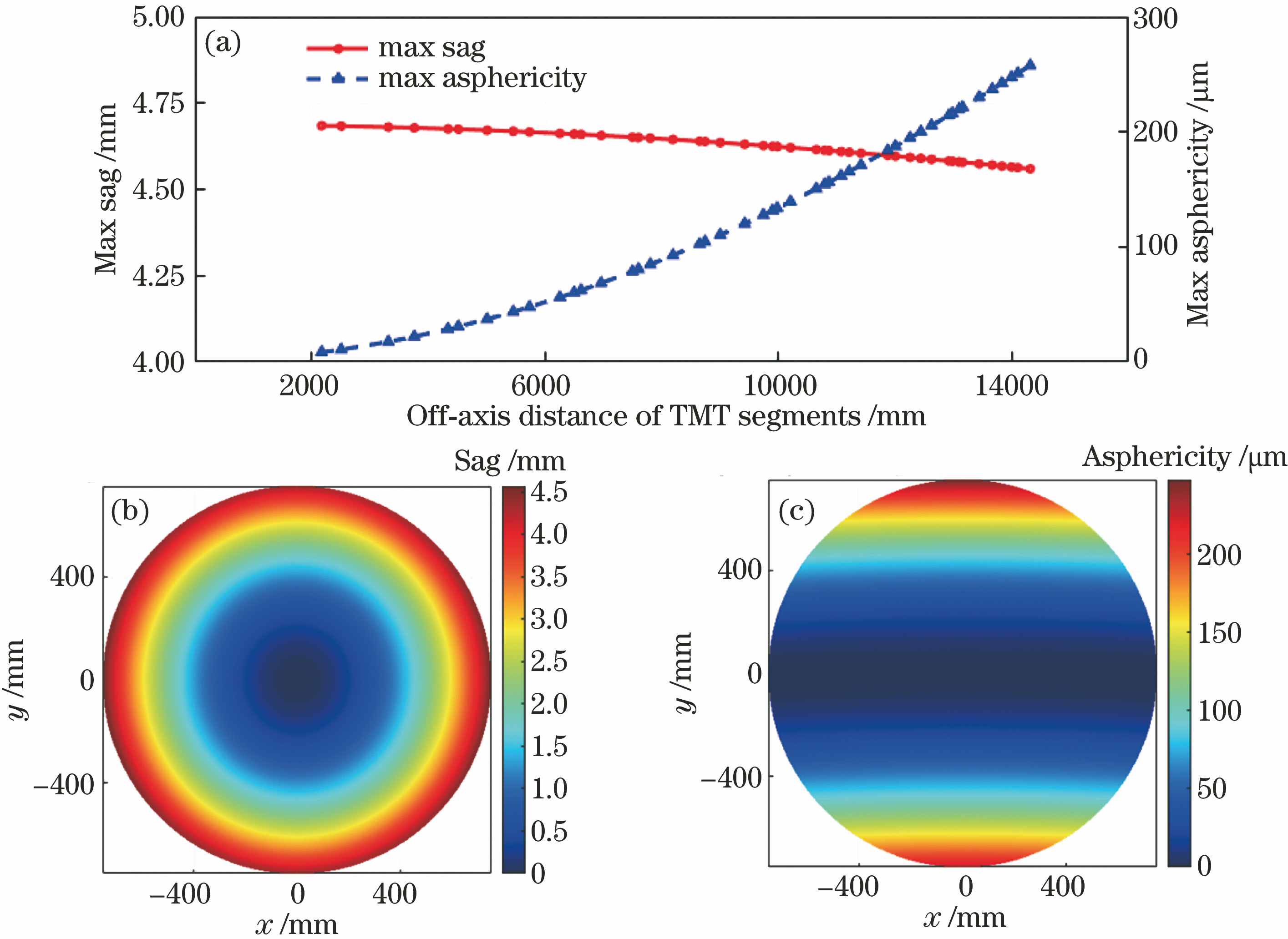
Fig. 1. Primary mirror sectors and segment numbering scheme of TMT
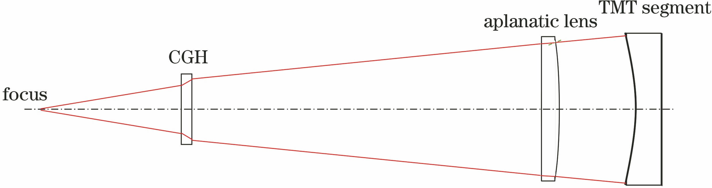
Fig. 2. Sag and asphericity of TMT segments after rotation and translation. (a) Max sag and max asphericity of TMT segments as functions of off-axis distance; (b) sag distribution and (c) asphericity distribution of TMT segment with off-axis distance of 13.99 m
Fig. 3. Measurement light path of refraction and diffraction mixed compensation using large aperture off-axis mirror
Fig. 4. Layout of aplanatic lens test
Fig. 5. Simulation of TMT segment test using refraction and diffraction mixed compensation. (a) Layout of simulation; (b) wavefront residual error; (c) spot diagram of multiple diffraction orders
Fig. 6. First 15 Zernike fringe polynomial coefficients of CGH phase function after normalization
Fig. 7. Distortion ratio of different off-axis TMT segments obtained by CGH refraction and diffraction mixed detection method and CGH direct detection method. (a) Distortion ratio as a function of off-axis distance obtained by different methods; (b) phase of CGH obtained by direction compensation for 13.99 m off-axis distance TMT segment; (c) phase of CGH obtained by refraction and diffraction mixed detection for 13.99 m off-axis distance TMT segment with lens
Fig. 8. Layout of CGH
Fig. 9. Simulation of trial CGH refraction and diffraction mixed compensation. (a) Phase distribution of CGH; (b) wavefront residual error
Fig. 10. Actual test optical path of CGH refraction and diffraction mixed compensation of trial mirror
Fig. 11. Test results of CGH refraction and diffraction mixed compensation of trial mirror. (a) Interferogram; (b) surface test result
Fig. 12. Test result calibration of trial mirror. (a) Error calibration of aplanatic lens; (b) surface test result of trial mirror after calibration
Fig. 13. Test result of trial mirror CGH autocollimation method
|
Table 1. Element adjustment tolerance and wavefront aberration change of testing system for refraction and diffraction mixed compensation
|
Table 2. Distortion ratio of different off-axis TMT segments obtained by CGH refraction and diffraction mixed detection method and CGH direct detection method
|
Table 3. Error of trial mirror test using refraction and diffraction mixed compensation

Set citation alerts for the article
Please enter your email address
© Copyright 2018-2021 | Chinese Laser Press. All Rights Reserved 沪ICP备15018463号-20