• Photonics Research
  • Vol. 10, Issue 4, 855 (2022)
Zhaojian Zhang1, Junbo Yang1、2、*, Te Du1, and Xinpeng Jiang1
Author Affiliations
  • 1College of Liberal Arts and Sciences, National University of Defense Technology, Changsha 410073, China
  • 2Center of Material Science, National University of Defense Technology, Changsha 410073, China
  • show less
    DOI: 10.1364/PRJ.443025 Cite this Article Set citation alerts
    Zhaojian Zhang, Junbo Yang, Te Du, Xinpeng Jiang. Topological multipolar corner state in a supercell metasurface and its interplay with two-dimensional materials[J]. Photonics Research, 2022, 10(4): 855 Copy Citation Text show less

    Abstract

    Second-order topological insulators (SOTIs) have recently attracted much attention due to their capability to support lower-dimensional topological states, namely, the corner states. Here, we demonstrate that properly designed supercell metasurfaces can support photonic corner states, meanwhile further serving as an ideal platform for the implementations of topological polaritons and dynamically reconfigurable corner states by assembling two-dimensional materials. Such metasurfaces consist of an array of finite-sized SOTIs mimicking the two-dimensional Su–Schrieffer–Heeger model. We reveal that the topological transition happens in unit cells without the bandgap, and nondegenerate multipolar corner states emerge in the supercell metasurface due to the inter- and intrasupercell coupling effects. Especially since these corner states are above the light line of the metasurface, we realize the collective stimulation of the two dipolar corner states and their superposition state via far-field excitation. By stacking monolayer hexagonal boron nitride film onto the metasurface, we further achieve the topological phonon polaritons through the strong coupling between the corner state and the phonon, which is confirmed by the Rabi splitting as well as anticrossing behavior emerging in the transmission spectra. Furthermore, we reveal the robustness of the corner state and strong coupling by introducing defects into the metasurface. Finally, tunable corner state and strong coupling with on-demand control are realized by assembling monolayer graphene onto the metasurface. Our theoretical study proposes a unique hybrid-material platform for topological polaritonics and reconfigurable topological photonics, which can promote large-area topological applications in practice.

    1. INTRODUCTION

    Topological insulators (TIs) were originally discovered in condensed-matter systems [1,2], and then further explored in various disciplines such as electronics [3], mechanics [4], and phononics [5]. In particular, we have recently witnessed the rise of topological photonics, which endows light with intriguing topological properties [68]. For example, topological edge states, the boundary states existing on the surfaces of TIs, are introduced as guide modes in photonic circuits, since they can support robust light-wave propagation immune to backscattering and perturbations, having potential applications in elevating transmission quality and efficiency of optical signals [9,10]. More recently, a new member of TIs, higher-order TIs (HOTIs), has drawn increasing attention due to the lower-dimensional gapless boundary states. For instance, two-dimensional (2D) second-order TIs (SOTIs) have a 1D edge and a 0D corner states. Distinct from the propagating nature of edge states, corner states are highly localized in the corner and have been identified in phononic, photonic, and circuit systems [1113]. Such a feature also provides a novel approach to trap light in photonic crystal (PhC) platforms [1416], and has been applied for exploring cavity quantum electrodynamics [17] as well as high-performance lasing [18,19].

    At the same time, strong coupling between light and matter has attracted much interest [20,21]. When the coherent energy exchange rate between photons and matter excitations exceeds their initial decay rates, they come to the strong-coupling regime and form the half-light, half-matter quasi-particles known as polaritons [22,23]. Up to now, strong coupling accompanied with polaritons has opened up new avenues for not only light manipulation but also modification of material properties and chemical reactions [2426]. Especially, when photons gather in topological states and strongly couple to matter, they give rise to topological polaritons [27,28]. For example, topological exciton-polaritons have emerged as a promising platform linking topological photonics and matter. Up to now, topological exciton-polaritons have been experimentally realized in GaAs microcavities and PhC slabs assembled with 2D materials, paving the way towards topological polaritonic devices [2932].

    Another remarkable research topic in topological photonics is endowing the topological states with the capability of on-demand dynamically reconfiguration, since it is essential in practical applications [33]. Nowadays, various schemes have been employed to realize tunable topological states, including mechanical control [34,35], liquid crystal reorientation [36,37], thermal-induced state transition of phase-change material [38], optical control based on free-carrier excitation in silicon [39], and modifying the defect strength [40]. Especially, as a typical 2D material, graphene also has potential applications in electrically reconfigurable topological devices, since its Fermi level, which is related to its material properties, can be readily tuned by externally applied voltage [41,42].

    Recent advances have revealed that topological states can exist as leaky states, namely, couple to the radiative continuum, in metasurfaces. Such non-Hermitian systems can be excited by far-field light sources and serve as a versatile platform for various applications such as topological invariant measurement [43], nonlinear effect enhancement [44], and topological polariton generation [31,32]. Thus, it is natural to wonder if it is feasible to introduce localized topological states to this system, since metasurfaces’ building blocks (meta-atoms) usually support localized modes [45,46]. In addition, on the side of strong coupling, there is growing interest in exploring the interaction between photons and lattice vibrations in polar materials [4749]. The accompanied phonon polaritons, with low-loss and energy-concentration features, may play an essential role in terahertz and mid-infrared polaritonic devices in the future [50,51]. More recently, one work has implemented the robust and unidirectional transport of the topological phonon polaritons by the strong coupling between the helical edge state and phonons in the mid-infrared [52]. However, the topological phonon polaritons mediated by corner states, which could provide a robust approach to localize phonons, have not been explored yet. Furthermore, from the application’s perspective, active control towards topological states and strong coupling is also indispensable.

    In this work, we demonstrate a supercell metasurface that supports localized corner states and investigate its interaction with monolayer hexagonal boron nitride (hBN) and graphene. The metasurface comprises periodically arranged PhC-slab SOTIs. Consequently, the corner states in supercells go beyond the light line due to the shrinking of the first Brillouin zone (FBZ) and can be stimulated by a far-field source. Via the plane-wave expansion (PWE) method, we show that the topological transition still exists even in the absence of the bandgap in unit cells, and nondegenerate multipolar corner states emerge due to the inter- and intrasupercell coupling effects. The full-wave simulation reveals that the two dipolar corner states, as well as their superposition state, can be collectively excited by a far-field plane-wave source in the mid-infrared regime, showing a sharp dip in the transmission spectrum. By integrating monolayer hBN with the metasurface, we further investigate the strong photon–phonon coupling between corner state and phonon in hBN via spectral dynamics, where the Rabi splitting and anticrossing features can confirm the occurrence of the strong coupling. The influences from material properties, as well as positions of hBN, are studied in detail. Moreover, the defect is introduced to test the topological protection of this structure. Finally, we show that by assembling monolayer graphene onto the metasurface, the resonant frequency of the corner state can be sufficiently tuned via modifying the Fermi level of the graphene so as to realize an electrically reconfigurable corner state and strong coupling. This work introduces a unique platform to the realm of topological photonics, and the resulting features could be applied to large-area topological phonon polaritonic devices and reconfigurable topological devices in the mid-infrared region.

    2. GEOMETRICAL CONFIGURATION OF SUPERCELL METASURFACES

    The geometrical configuration of a supercell metasurface is shown in Fig. 1. It is composed of periodically arranged PhC-slab supercells along the x and y directions, each of which consists of a finite number of square unit cells, as defined in Fig. 1. The lattice constants of the unit cell and supercell are a and 5a, respectively. Here we set a=2.03  μm so that the corner states will be located in the mid-infrared region. The height of the metasurface is H=4.245  μm. The material of the metasurface is chosen as silicon, whose dispersionless dielectric constant is ε=11.7 in the mid-infrared region [53]. As presented in Fig. 1, there is a square region filled with nontrivial unit cells (highlighted in blue) surrounded by trivial unit cells (highlighted in gray) in each supercell, where m represents the number of trivial rows between neighboring nontrivial regions and n denotes the number of nontrivial rows in one supercell. Here, the “nontrivial” and “trivial” refer to the topological nontrivial and trivial phases that unit cells possess, respectively, which will be discussed in the following section.

    Geometric configuration of the supercell metasurface. The metasurface consists of periodically arranged supercells along x and y directions, which include nontrivial and trivial unit cells highlighted in blue and gray, respectively. There is an x-polarized plane wave that is incident on the metasurface. The inset shows the schematic of the supercell.

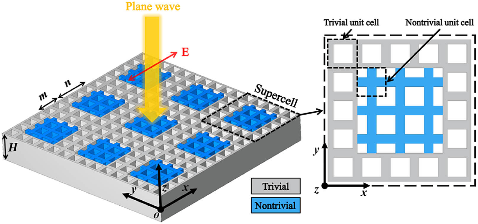
    Figure 1.Geometric configuration of the supercell metasurface. The metasurface consists of periodically arranged supercells along x and y directions, which include nontrivial and trivial unit cells highlighted in blue and gray, respectively. There is an x-polarized plane wave that is incident on the metasurface. The inset shows the schematic of the supercell.

    3. BAND STRUCTURES AND TOPOLOGICAL PROPERTIES

    To reveal the topological properties of different 3D unit cells, first, we employ the PWE method to compute photonic band structures of PhC-slabs with these unit cells; the calculated results are summarized in Fig. 2. Notably, here only the transverse electric (TE) modes are considered in the calculation, because the bandgaps, which play an important role in the topological transition, are favored for TE modes in such connected periodic structures [54].

    (a)–(c) Schematics of cross sections in the x−y plane for the three unit cells. The yellow and white areas represent silicon and air regions, respectively. The FBZ is given in (a). (d)–(f) The TE bands of PhC-slabs with unit cells in (a)–(c), respectively, where the gray region indicates the light cone, and the bands in gray represent higher-order state bands. In (d) and (f), the insets are Hz field profiles at X point. The blue and red band colors indicate the band inversion of the two fundamental state bands, and symbols + and – represent even and odd parity of Hz, respectively. In (e), the green band color highlights the degenerated fundamental state bands.

    Figure 2.(a)–(c) Schematics of cross sections in the xy plane for the three unit cells. The yellow and white areas represent silicon and air regions, respectively. The FBZ is given in (a). (d)–(f) The TE bands of PhC-slabs with unit cells in (a)–(c), respectively, where the gray region indicates the light cone, and the bands in gray represent higher-order state bands. In (d) and (f), the insets are Hz field profiles at X point. The blue and red band colors indicate the band inversion of the two fundamental state bands, and symbols + and – represent even and odd parity of Hz, respectively. In (e), the green band color highlights the degenerated fundamental state bands.

    The primary unit cell, as shown in Fig. 2(a), contains four identical square air holes with side length l=0.34a, clustering together at the center of the unit cell. Our model emulates the 2D Su–Schrieffer–Heeger (SSH) model, whose Hamiltonian is as follows [14]: H=(0h12h130h12*00h24h13*00h340h24*h34*0),where h12=h34=ta+tbexp(ikx), and h13=h24=ta+tbexp(iky). Here, k=(kx,ky) is the wave vector, ta and tb are intra- and intercell hopping among atoms in the SSH model. In our PhC unit cell, the four holes play the role of the atoms in the SSH model, and shifting the holes along the diagonal of the unit cell will tune the intra- and intercell optical coupling, serving as the analog of hopping modulation in the SSH model.

    Following the scheme mentioned above, we move the four holes outwardly along the diagonal of the unit cell, as shown in Figs. 2(a)–2(c), and observe the evolution of the corresponding band structures in FBZ, as presented in Figs. 2(d)–2(f) (only bands below the light line are included). In Figs. 2(d) and 2(f), there is no bandgap. However, we find two bands, highlighted in blue and red, respectively, that resemble the first two bands of the 2D counterpart of the unit cells, i.e., the 2D unit cells with infinite height. The Hz field distributions of these two bands at symmetry points are similar to those of 2D unit cells (see Appendix A). The only difference is that the bandgap, which exists in band structures of 2D unit cells, is populated with several emerged bands (highlighted in gray) in the band structures of 3D unit cells. Furthermore, we find that the two bands are fundamental state bands with no nodal plane along the z axis, whereas those emerged bands are higher-order state bands, which possess more than one nodal plane along the z axis (see Appendix B). Previous studies have revealed the existence of these higher-order state bands, which are known as photonic subbands [55,56]. These states result from the confinement of optical fields within the slab, and can be regarded as the higher-order guide modes in a uniform slab distorted by in-plane hole lattices [56]. When the PhC-slab is thin, these states are located at higher frequencies than fundamental states due to the lower effective refractive index (neff). Lifting the height of the slab will increase the neff of all states and redshift them. However, the neff of higher-order states are more sensitive to such change, so they will gradually fall into and cancel the fundamental bandgap [5658], leading to the consequences shown in Figs. 2(d) and 2(f).

    Next, we focus on the two fundamental state bands of 3D unit cells. The field distributions of Hz of the two bands at the X point are shown in the insets of Figs. 2(d) and 2(f), obtained in the xy plane crossing through the middle of the unit cell and perpendicular to the z axis. Note that Hz field profiles in the same xy cross section will be shown in the following section unless stated otherwise. In Fig. 2(d), the Hz of the first band has even parity (represented by the symbol + in the inset, and indicated in blue band color), whereas another band has odd parity (represented by the symbol – in the inset, and indicated in red band color). As the four holes are moved outwardly along the diagonal until they occupy the four quadrants of the unit cell symmetrically, as shown in Fig. 2(b), the two bands are degenerate along the XM crystal symmetry axis, as depicted in Fig. 2(e). When the four holes continue moving outwards to the edges of the unit cell as shown in Fig. 2(c), the corresponding band structures are depicted in Fig. 2(f), which are identical to those in Fig. 2(d). Nevertheless, the parity of Hz in Fig. 2(f) displays the opposite behavior. Such parity inversion reveals that even when the emerged higher-order state bands populate the bandgap, they will not interfere with the behavior of the two fundamental state bands. The two bands still have been inverted, accompanied by the topological phase transition. This topological phase transition is characterized by the 2D Zak phase, which is defined as follows [14]: θα=2πPα=12πFBZTr[Aα(k)]dk,α=x,y,Here, P=(Px,Py) represents the 2D polarization, and Aα(k)=iψk|kα|ψk is the Berry connection. In the 2D unit cell, |ψk2D is the eigenstates of all the bands below the bandgap, namely, the eigenstates of the first band. Since the band inversion of the 3D unit cell is very similar to that in the 2D case, here, we define |ψk as the eigenstates of the first fundamental state band. The calculated results show that the unit cell in Fig. 2(a) has a 2D Zak phase (0, 0), meaning that it possesses a trivial topological phase. In contrast, the Zak phase is (π, π) for the unit cell in Fig. 2(c), indicating that it has a nontrivial topological phase. The details of this calculation are given in Appendix C.

    4. FAR-FIELD COLLECTIVE EXCITATION OF TOPOLOGICAL DIPOLAR CORNER STATES

    Previous studies of SOTIs have realized topological corner states in the finite square PhC-slabs, comprising nontrivial unit cells surrounded by trivial unit cells [14,15,19]. There are four multipolar corner states in the bandgap with degenerate eigenfrequencies, namely, monopole, dipole I, dipole II, and quadrupole states [19]. Meanwhile, these corner states are protected by nontrivial topology, and characterized by the topological corner charge Qc=4PxPy=1, where Px and Py are 2D polarization of the nontrivial unit cell [14]. Differently, in this work, we extend SOTIs to be periodic along the x and y axes, so that each SOTI acts as a supercell and a metasurface is formed, as shown in Fig. 1. When the number of trivial and nontrivial rows is m=2 and n=3, respectively, we obtain four corner states at Γ point of the metasurface, of which eigenfrequencies are in the gap between the first two fundamental state bands of the unit cells. The corresponding Hz profiles are presented in the insets of Fig. 3(a). It is shown that the fields of these coupled corner states are highly localized at the corners of each supercell, and the distributions are consistent with the definition of multipolar corner states in Ref. [19]. At Γ point, the dipole I and dipole II states have degenerate eigenfrequencies. However, monopole and quadrupole states are nondegenerate, a feature that is distinct from the conventional corner states in an isolated SOTI. Such periodically coupled topological states have also been reported in previous works [43,59].

    (a) Projected band structures of the metasurface along the kx direction when m=2 and n=3. The Hz profiles of the bands at Γ point are plotted in the insets. (b) Dependence of the eigenfrequencies at Γ point on m when n=5; (c) dependence of the eigenfrequencies at Γ point on n when m=4; (d) transmission spectra of the metasurface with different heights H; the insets show Hz distributions of the field at the transmission dip in the x−y and x−z cross sections, respectively. (e) Normalized scattering cross sections of the finite SOTI square arrays with different sizes. (f) Q factor of the finite SOTI array with the total number of supercells. The yellow and gray dashed lines indicate the Q factor of the infinite array and single isolated supercell, respectively.

    Figure 3.(a) Projected band structures of the metasurface along the kx direction when m=2 and n=3. The Hz profiles of the bands at Γ point are plotted in the insets. (b) Dependence of the eigenfrequencies at Γ point on m when n=5; (c) dependence of the eigenfrequencies at Γ point on n when m=4; (d) transmission spectra of the metasurface with different heights H; the insets show Hz distributions of the field at the transmission dip in the xy and xz cross sections, respectively. (e) Normalized scattering cross sections of the finite SOTI square arrays with different sizes. (f) Q factor of the finite SOTI array with the total number of supercells. The yellow and gray dashed lines indicate the Q factor of the infinite array and single isolated supercell, respectively.

    Such nondegeneracy mainly results from the interaction of the optical fields at corners, namely, the inter- (between neighboring supercells) and intrasupercell (within the same supercell) optical coupling among the corner states [19,59]. To reveal this point, first, we tune m from 1 to 5 and keep n at 5, and thus the intersupercell coupling strength is gradually weakened while the intrasupercell coupling strength maintains unchanged. As m increases, the eigenfrequencies of multipolar corner states at Γ point converge asymptotically to a common value that corresponds to the eigenfrequency of the degenerate corner states in an isolated SOTI, as shown in Fig. 3(b). The same convergence manner can be found if n is varied from 2 to 6 while m is fixed at 4, as presented in Fig. 3(c). These phenomena indicate that these corner states will become degenerate if the coupling effects vanish, proving that the coupling effects will break the degeneracy of the corner states.

    In particular, the periodicity of the metasurface endows the corner states with band structures, as shown in Fig. 3(a), which are given along the kx direction. Due to a lack of bandgap, these bands are embedded in the surrounding higher-order bulk bands that are not shown here, but do not hybridize with them. It is shown that these bands are symmetric to Γ point, and display strong frequency dispersion. In addition, the sign of the group velocity for the monopole and dipole II bands is opposite to that for dipole I and quadrupole bands, which is explained by the opposite convexity of the corresponding bands. Interestingly, the degeneracy of the two dipolar corner states can be broken upon the variation of kx.

    In addition, the corner states in this metasurface are far beyond the light line because the metasurface, whose lattice constant is 5a, possesses shrinking FBZ compared with the system with lattice constant a, which will lead to the shrinking of the light cone. Thus, these corner states come to the continuum, become radiative, and couple to the external excitations. To reveal this, we perform a full-wave simulation based on the finite-difference time-domain (FDTD) method. In the simulated domain, the supercell is modeled with periodic conditions in the ±x and ±y directions and perfectly matched layers (PMLs) in the ±z directions. The far-field excitation is introduced by an x-polarized plane wave source at the top of the supercell, propagating along z direction, as shown in Fig. 1. One 2D power monitor across the xy plane is placed under the metasurface, and the total transmitted power Pt is collected by integrating the power across the surface of the monitor. The normalized transmission spectrum is calculated by T(ω)=Pt(ω)/Ps(ω), where Ps represents the power of the light source.

    The transmission spectra of the metasurface with different height H under the normal incidence are shown in Fig. 3(d). When H=4.245  μm, there is a transmission dip at 1387.21  cm1 (0.282a/λ), which corresponds to the eigenfrequencies of dipole I and dipole II states in Fig. 3(a) at Γ point. It is a leaky state (resonant state) that is efficiently excited by the external stimulation, and the interference between the resonant state and the incoming plane wave gives rise to the Fano profile of the transmission spectrum [60], TFano=|a1+ia2+bωω0+iγ|2,where a1, a2, and b represent real constant parameters, ω0 represents the resonant frequency, and γ represents the damping rate of the resonance. By fitting the transmission spectrum with this Fano formula, the quality (Q) factor can be calculated following the relation Q=ω0/2γ. Here, the Q factor of this resonance is 3022. In addition, the resonant frequency of the state can be slightly tuned by changing the height of the metasurface, as indicated in Fig. 3(d).

    We further confirm that this resonant state is a dipolar corner state by investigating the field profile at the resonant frequency, as presented in the insets of Fig. 3(d). The Hz distribution in the xy cross section shows that the field is localized at four corners of the supercell, which is the superposition state of dipole I and dipole II states. The reason for the emergence of this state is that the eigenfrequencies of dipole I and dipole II states degenerate at Γ point, and the field profiles of the two states can match the spatial symmetry of the incident plane wave polarization simultaneously, which is odd under 180° rotation around the z axis. Especially, by rotating the polarization direction of the plane wave, we also successfully excite the two dipolar states separately (see Appendix D). In addition, the Hz distribution in the xz cross section of the dipolar corner state shows that the field is primarily confined in the metasurface. The other two corner states, monopole and quadrupole states, however, cannot be excited owing to the symmetry mismatch, namely, zero overlap between their field profiles and incident waves. Since these two states are localized states beyond the light line, and do not couple to the continuum, they exist as bound states in the continuum (BICs).

    What is more, the collective nature of the corner states in metasurface is revealed by investigating the responses of finite SOTI square arrays with different sizes of N×N, where N2 represents the total number of supercells. The normalized scattering cross sections and extracted Q factors of these finite arrays are plotted in Figs. 3(e) and 3(f), respectively. The Q factor of the dipolar corner state in an isolated supercell is only 152, as marked in Fig. 3(f). However, as the size of the finite array increases, the generated scattering cross section becomes narrower, and the peak approaches the resonant frequency of the infinite array, as shown in Fig. 3(e). Meanwhile, the corresponding Q factor rises exponentially toward the Q factor of the infinite array, as illustrated in Fig. 3(f). These features indicate a collective response of the metasurface; in other words, the response is not a sum of the individual supercell responses [6163]. Such collective behavior arises from the coherent coupling between neighboring supercells, which can lead to the synchronous oscillations of the corner states in all supercells. The size-dependent Q factor results from the truncation of the collective behavior caused by the finiteness of the array and will reach the level of the infinite array when the array is sufficiently large. Previous studies have revealed that such collective states can emit light with high spatial coherence, which can be applied for large-area lasing [64].

    5. STRONG COUPLING BETWEEN DIPOLAR CORNER STATE AND LATTICE VIBRATIONS

    In this section, we present the strong coupling effect between dipolar corner states in an infinite array and lattice vibrations. The lattice vibrations, namely, phonons, are introduced by covering a monolayer hBN film (called hBN for simplicity in the following) onto the metasurface, as presented in the inset of Fig. 4(a). The surface conductivity model of hBN is as follows [65]: σhBN(ω)=4iε0ωωTOvgωTO2ω2iωγp.Here, ε0 is the vacuum permittivity, and vg is the phonon group velocity with the value of 1.2×10⁴c, where c is the light speed in vacuum. Due to the absence of splitting between longitudinal and transverse optical (LO and TO) phonons, hBN possesses degenerate optical phonon frequency ωTO at 1387  cm1 [66]. The intrinsic damping rate of phonon, represented by γp, can be artificially regulated by the isotopic enrichment of hBN [67]. Here, γp is primarily set as 2  cm1; different values will be discussed in this section.

    (a) The transmission spectra of hBN (blue curve), metasurface (red curve), and metasurface covered by hBN (yellow curve), under the plane-wave excitation. The inset shows the schematic of the metasurface integrated with hBN. (b) Energy diagram of the hybridization due to the strong coupling;. (c) |H| distributions of the two polariton states at 1385.09 cm−1 and 1389.02 cm−1, respectively; (d) transmission spectra under different heights H while the phonon frequency ωp is kept as 1387 cm−1. (e) Frequencies of the two polariton branches ω± as a function of the frequency of the corner state ωc; the calculated results from FDTD (dots) and CHOM (curves) are plotted. ωp remains unchanged, as indicated by the green dashed line. (f), (g) The fractions of the corner state and phonon in upper and lower branches, respectively.

    Figure 4.(a) The transmission spectra of hBN (blue curve), metasurface (red curve), and metasurface covered by hBN (yellow curve), under the plane-wave excitation. The inset shows the schematic of the metasurface integrated with hBN. (b) Energy diagram of the hybridization due to the strong coupling;. (c) |H| distributions of the two polariton states at 1385.09  cm1 and 1389.02  cm1, respectively; (d) transmission spectra under different heights H while the phonon frequency ωp is kept as 1387  cm1. (e) Frequencies of the two polariton branches ω± as a function of the frequency of the corner state ωc; the calculated results from FDTD (dots) and CHOM (curves) are plotted. ωp remains unchanged, as indicated by the green dashed line. (f), (g) The fractions of the corner state and phonon in upper and lower branches, respectively.

    The transmission spectrum of the suspended hBN under the plane-wave excitation is shown by the blue curve in Fig. 4(a), and there is a transmission dip at 1387  cm1, which indicates the existence of the phonon. For comparison, the transmission spectrum of the dipolar corner state in the metasurface with H=4.245  μm is also plotted in Fig. 4(a) as the red curve. The spectral overlap of the corner state and the phonon can facilitate coherent coupling between them.

    With hBN laid on the top of the metasurface, a hybrid silicon–hBN metasurface is constructed, and a spectral splitting, namely, Rabi splitting, is observed in the transmission spectrum, as shown by the yellow curve in Fig. 4(a). There are two emerged transmission dips at 1385.09  cm1 and 1389.02  cm1, which indicates the formation of two new states. As depicted in Fig. 4(b), the two new states are lower-energy (ω) and upper-energy (ω+) hybridized photon–phonon states, namely, topological phonon polariton states, which are the result of strong light–matter interaction between the photonic corner state and the phonon in hBN. A transmission dip at 1387.06  cm1 still exists in the spectrum, representing nonhybridized photons and phonons remaining in the system [68]. In addition, the |H| distributions of the two polariton states still maintain the profiles of the corner state, as presented in Fig. 4(c). The condition of strong coupling is as follows [20]: C=Ω2Γc22+Γp22>1,where C is the strong-coupling factor, Ω is the Rabi splitting, and Γc and Γp are linewidths of the corner state and phonon, respectively, indicating the total damping rate induced by both radiative and intrinsic losses, and can be extracted from the corresponding transmission spectrum by fitting the Fano formula. Here, we get Ω=3.9  cm1, Γc=0.46  cm1, and Γp=2.35  cm1; thus, C=5.31>1, and the strong-coupling condition is fully fulfilled.

    To analytically describe the coupling of the corner state and phonon, the coupled harmonic oscillators model (CHOM) is employed, in which the corner state and phonon are regarded as two coupled harmonic oscillators [6971]. The two eigenfrequencies ω± in this model, representing the two new polariton states, can be described as follows: ω±+iΓ±2=ωc+ωp2iΓc+Γp4±124g2+(ωcωpiΓcΓp2)2,where ωc (ωp) represents the resonant frequency of the corner state (phonon), and g is the coupling strength equal to Ω/2. Furthermore, we slightly tune the resonant frequency of the corner state ωc by changing the height H; the corresponding transmission spectra are depicted in Fig. 4(d). An anticrossing behavior, another typical feature of strong coupling, is observed between the two polariton branches in Fig. 4(d), further proving that it is indeed in the strong-coupling regime. The ω± as a function of ωc are plotted in Fig. 4(e), showing that the numerical results can be fitted well by the analytical model where g is treated as a free-fitting parameter. Additionally, as ωc shifts, the weight of the corner state and phonon in upper and lower branches can be calculated as follows [72]: |α|2=12(1±ΔΔ2+4g2),|β|2=12(1ΔΔ2+4g2),where Δ is the frequency detuning of ωc relative to the primitive value 1387.21  cm1; the corresponding results are shown in Figs. 4(f) and 4(g), respectively. It is shown that in the upper branch, the fraction of the corner state increases and the fraction of the phonon decreases as the detuning varies from positive to negative, as shown in Fig. 4(f), whereas the lower branch possesses the opposite behavior, as shown in Fig. 4(g). When Δ=0, the corner state and phonon contribute equally to the two polariton states.

    To gain deeper physical insights into the strong coupling, the hBN is moved from the top (z=H/2) to the middle of the metasurface (z=0). The corresponding transmission spectra under different H are depicted in Fig. 5(a), and the ω± as a function of ωc are plotted in Fig. 5(b). Interestingly, a Rabi splitting Ω=7.24  cm1 is achieved, and the anticrossing feature becomes more significant, as indicated in Figs. 5(a) and 5(b). Evidently, the strong coupling is further enhanced when the hBN comes to the middle of the metasurface. This is because the field of the corner state is concentrated more in the middle, as indicated in the inset of Fig. 3(d), and strong coupling will benefit from such local field enhancement [21]. In addition, the spatial overlap between the field and hBN increases, and more phonons will participate in the interaction, which will also contribute to the enhancement of the strong coupling.

    (a) The transmission spectra under different heights H when hBN is at z=0. The phonon frequency ωp is kept as 1387 cm−1. (b) The frequencies of the two polariton branches ω± as a function of the corner state ωc when hBN is at z=0. The calculated results from FDTD (dots) and CHOM (curves) are plotted. ωp remains unchanged, as indicated by the green dashed line. (c) The Rabi splitting Ω under different phonon damping rates γp and hBN positions of the metasurface along the z axis; the missing data points represent the vanishing of Rabi splitting. (d) The strong-coupling factor C under different γp and hBN positions along the z axis; (e) Rabi splitting Ω and the strong-coupling factor C with hBN film or crystal at different positions of the metasurface along the z axis.

    Figure 5.(a) The transmission spectra under different heights H when hBN is at z=0. The phonon frequency ωp is kept as 1387  cm1. (b) The frequencies of the two polariton branches ω± as a function of the corner state ωc when hBN is at z=0. The calculated results from FDTD (dots) and CHOM (curves) are plotted. ωp remains unchanged, as indicated by the green dashed line. (c) The Rabi splitting Ω under different phonon damping rates γp and hBN positions of the metasurface along the z axis; the missing data points represent the vanishing of Rabi splitting. (d) The strong-coupling factor C under different γp and hBN positions along the z axis; (e) Rabi splitting Ω and the strong-coupling factor C with hBN film or crystal at different positions of the metasurface along the z axis.

    The material properties of the hBN also play an important role in this strong coupling. To study this, we tune the phonon damping rate γp of the hBN from 1 to 5  cm1, meanwhile adjusting the position of the hBN from the top to the middle of the metasurface. The induced Rabi splitting Ω and strong-coupling factor C are plotted in Figs. 5(c) and 5(d), respectively. Notably, the missing data points represent the vanishing of Rabi splitting. As shown in Fig. 5(c), the higher phonon damping rate will lead to the decline of the Rabi splitting, provided hBN is at the same position. It is because a higher phonon damping rate means a shorter lifetime of the phonon, which will reduce the interaction time between photons and phonons. It is also shown that moving the hBN from the top to the middle will gradually enhance the Rabi splitting due to the field enhancement, and Rabi splitting is always visible for hBN at any position when γp is within 13  cm1. Notably, Fig. 5(d) indicates that the strong-coupling condition is fulfilled for any case plotted in Fig. 5(c), showing that such a hybrid metasurface can serve as an ideal platform for strong coupling. In addition, a similar evolution of Ω and C can be expected for the position of hBN from z=0 to z=H/2 due to the symmetry of the field distribution along the z axis.

    Moreover, hBN may be etched together with the metasurface in practical fabrication. Thus, we further investigate the strong coupling under the condition that hBN with γp=2  cm1 is etched into a crystal with the same pattern as the metasurface. In this case, Rabi splitting is also observable, and strong coupling happens for the hBN crystal at any position, as indicated in Fig. 5(e). However, for the metasurface with hBN film or crystal at a specific position, the former always possesses a larger Rabi splitting and strong-coupling factor than the latter. This is because the hBN crystal has a smaller area than the film, so fewer phonons will get involved in the photon–phonon interaction, leading to the weaker strong coupling.

    6. TOPOLOGICALLY PROTECTED STRONG COUPLING

    One of the most attractive features of topological photonic systems is their immunity to perturbations [810]. To investigate such topological protection characteristics of this metasurface, one square defect with side length l is introduced in different positions of the supercell for every 3×3 arrays, as presented in Fig. 6(a). Taking defect 1 as an example for the metasurface with no hBN, the transmission spectra under different defect lengths l are plotted in Fig. 6(b). It is shown that as l varies from 0 to 0.69 μm, the spectrum maintains a consistent line shape, and the transmission dip has a slight blueshift, introducing the frequency detuning Δ. In Fig. 6(c), we present the frequency detuning induced by defects in different positions. It is shown that the frequency shift will be more significant with a larger defect, but the maximum detuning is only 0.73  cm1. The exception is defect 4, which has a negligible influence on the resonant frequency. These defects are further introduced in the hybrid metasurface. Here we only consider the largest defect because it will lead to the strongest perturbation in the strong coupling. With defects 1 to 3, the two emerged dips also exhibit a slight blueshift, as shown in Fig. 6(d); nevertheless, the Rabi splitting can still be identified, leading to the strong-coupling factor of 5.86, 6.45, and 6.15, respectively. Defect 4 causes little disturbance to strong coupling. Thus, the strong-coupling condition is still fulfilled in all cases. These results indicate that the corner state is topologically protected to a certain extent, and the induced tolerance further ensures the robustness of the strong coupling.

    (a) Schematic of the defects with side length l′ in the supercell. The number labels the defects in different positions of the supercell. (b) Transmission spectra of the metasurface with defect 1 under different l′; the black dashed line indicates the position of the dip without defects. (c) frequency detuning induced by defects in different positions with respect to l′; (d) transmission spectra of the hybrid metasurface with defects in different positions. Here, l′=0.69 μm for all defects. The black dashed lines indicate the positions of the dips without defects.

    Figure 6.(a) Schematic of the defects with side length l in the supercell. The number labels the defects in different positions of the supercell. (b) Transmission spectra of the metasurface with defect 1 under different l; the black dashed line indicates the position of the dip without defects. (c) frequency detuning induced by defects in different positions with respect to l; (d) transmission spectra of the hybrid metasurface with defects in different positions. Here, l=0.69  μm for all defects. The black dashed lines indicate the positions of the dips without defects.

    7. DYNAMICALLY RECONFIGURABLE CORNER STATE AND STRONG COUPLING UTILIZING GRAPHENE

    In the last section, we show that the resonant frequency of the corner state and the strong coupling can be dynamically tuned by stacking monolayer graphene film onto the metasurface. The surface conductivity model of graphene in the mid-infrared is described by the Drude-like model [73], σgra(ω)=ie2|EF|π2(ω+iγe).

    Here, e represents the electron charge, EF represents the Fermi level, is the reduced Planck’s constant, and γe is the electron damping rate set as 10  ps1, according to previous reports [74]. The height of the metasurface H is maintained at 4.245 μm.

    The transmission spectra of the hybrid metasurface shown in the inset of Fig. 7(a) are plotted in Fig. 7(a). It is shown that the resonant frequency of the corner state remains at 1387.21  cm1 when the Fermi level of graphene is at 0.1 eV; nonetheless, the Q factor of the state is reduced from 3022 to 1950, compared with the case of no graphene, as indicated by the blue and red curves in Fig. 7(a). It is because graphene introduces additional losses that suppress the lifetime of the corner state. However, if the Fermi level is lifted to 1.0 eV, the resonant frequency will shift to 1388.48  cm1, as indicated by the yellow curve in Fig. 7(a). Further blueshift of the resonant frequency happens when the Fermi level increases to 2.0 eV, as indicated by the purple curve in Fig. 7(a). We also notice that the Q factor of the corner state will drop as the Fermi level increases because the higher Fermi level will lead to the larger real part of the graphene conductivity, as indicated in Eq. (8), which means more losses will be introduced. It should be mentioned that the Fermi level of the graphene can be flexibly tuned by applying voltage externally [41].

    (a) The transmission spectra of the metasurface with no graphene (blue curve), with top-covered graphene at 0.1 eV (red curve), 1.0 eV (yellow curve), and 2.0 eV (purple curve). The inset shows the schematic of the metasurface integrated with graphene. (b) Transmission spectra under different Fermi levels of graphene when graphene is at z=H/2; (c) resonant frequency of the corner state ωc under different Fermi levels of graphene when graphene position moves along the z axis; the case when graphene crystal is at z=H/2 is also plotted. (d) Transmission spectra under different Fermi levels of graphene when hBN–metasurface–graphene heterostructure is introduced. The inset shows the schematic of the heterostructure.

    Figure 7.(a) The transmission spectra of the metasurface with no graphene (blue curve), with top-covered graphene at 0.1 eV (red curve), 1.0 eV (yellow curve), and 2.0 eV (purple curve). The inset shows the schematic of the metasurface integrated with graphene. (b) Transmission spectra under different Fermi levels of graphene when graphene is at z=H/2; (c) resonant frequency of the corner state ωc under different Fermi levels of graphene when graphene position moves along the z axis; the case when graphene crystal is at z=H/2 is also plotted. (d) Transmission spectra under different Fermi levels of graphene when hBN–metasurface–graphene heterostructure is introduced. The inset shows the schematic of the heterostructure.

    Further investigation shows that the resonant frequency of the corner state can be continuously tuned by changing the Fermi level of graphene, as presented in Fig. 7(b). With the range of the Fermi level from 0.2 to 2.0 eV, the resonant frequency can be continuously altered from 1387.56 to 1389.80  cm1, with a significant frequency detuning of 2.24  cm1. Such frequency variation can be attributed to the change of the effective permittivity of the graphene, which is caused by different Fermi levels. It will partly modify the permittivity of the surrounding environment and further influence the resonant frequency of the corner state, since the electric field of the corner state decays exponentially on the surface of the metasurface along the z direction. According to simplified perturbation theory, the frequency detuning Δω of the corner state can be described as follows [75]: ΔωωcΔεgratgradfield,where tgra is the equivalent thickness of the graphene, and dfield is the penetration depth of the electric field. εgra is the in-plane effective permittivity of the graphene, which can be expressed as follows [76]: εgra=2.5+iσgraε0ωtgra.

    Now we see that as the Fermi level rises, the real part of εgra will also increase, resulting in positive Δεgra as well as the positive Δω, which corresponds to the blueshift in the spectrum.

    To gain more insights into this structure, we study the influence of graphene position along the z-axis on the frequency detuning. The relations between the resonant frequency of the corner state and Fermi level under different positions of graphene are presented in Fig. 7(c). It is shown that as the graphene comes from the top to the middle of the metasurface, the frequency detuning is gradually enhanced with the Fermi level from 0.2 to 2.0 eV. Especially, when graphene is in the middle, the frequency detuning is 6.36  cm1, almost 3 times that when graphene is on the top. In addition, we also investigate the case when graphene crystal is on the top of the metasurface, and the consequent detuning is 2.05  cm1, slightly lower than the case with graphene film on the top. All the results indicate that the larger overlap between graphene and the field of the corner state plays an important role in enhancing detuning performance.

    Finally, the reconfigurable strong coupling is realized by assembling hBN (γp=2  cm1) and graphene into the metasurface simultaneously, as illustrated in the inset of Fig. 7(d). Since the field of the corner state is symmetric to the xy plane, placing graphene at the bottom of the metasurface will exhibit the same tunability as placing it on the top. We tune the height H to be 4.275 μm so that the resonant frequency of the corner state will match the phonon frequency when the Fermi level of the graphene is 1.0 eV. On this basis, the anticrossing behavior can be observed by altering the Fermi level from 0.2 to 2.0 eV, as displayed in Fig. 7(d), which arises from the frequency detuning of the corner state shown in Fig. 7(b). The strong-coupling factor here is 5.08, which meets the strong-coupling condition but is slightly lower than the case with no graphene. This attributes to the extra losses introduced by graphene, which increases the initial damping rate of the corner state. Such an hBN–metasurface–graphene heterostructure provides a feasible platform to realize the active control of strong coupling.

    8. CONCLUSION

    In summary, we propose a specially designed supercell metasurface composed of periodically arranged SOTIs based on a 2D SSH model, which supports nondegenerate topological multipolar corner states in the mid-infrared, and the two dipolar corner states, as well as their superposition state, can be directly excited by a far-field source due to the symmetry matching. By covering the metasurface with the hBN, topological phonon polaritons are realized through strong coupling between the corner state and phonon, indicated by Rabi splitting and anticrossing behavior. We further study the robustness of the corner state and strong coupling that originates from the topological protection. Finally, graphene is employed to realize dynamically reconfigurable corner states and strong coupling with on-demand electric control.

    Extending isolated SOTI to be an array can promote novel large-area applications with topological protection. For example, with the assistance of the gain media, these collectively excited corner states can act as a large number of coherently coupled photonic emitters and form a laser array with large out-of-plane-emitting conformal aperture, which are of special importance for next-generation applications such as optical communication and light detection and ranging (lidar) [77,78]. Meanwhile, the thin analyte or nonlinear materials supported on the large-area surface of the array can interact sufficiently with light due to the in-plane field confinement, which can benefit the applications in label-free biosensing and optical nonlinear enhancement [79,80]. Moreover, recently emerging works have unveiled the connection between corner states and BICs [81], and nonlinear control of them has also been proposed [82]. Thus, the possibility to turn the two BICs in this metasurface system (monopole and quadrupole corner states) into leaky quasi-BICs is also worth exploring. Finally, the hybrid silicon-2D material metasurfaces have potential applications for topological polaritonic devices and reconfigurable topological devices in the mid-infrared region.

    APPENDIX A: BAND STRUCTURES OF 3D AND 2D UNIT CELLS

    In this section, we compare the TE band structures of the 3D unit cells in Figs. 2(a)–2(c) of the main text with those of the corresponding 2D unit cells, namely, 3D unit cells with infinite height along the z axis. Figures 8(a)–8(c) show the band structures of the 3D unit cells, and the corresponding Hz field distributions of the two fundamental state bands (highlighted in colors) at symmetry points are shown in Figs. 8(d)–8(f), obtained in the xy plane crossing through the middle of the unit cells and perpendicular to the z axis. Correspondingly, the band structures and field distributions at symmetry points of the 2D unit cells are presented in Figs. 9(a)–9(f). It is shown that the profiles of the two fundamental state bands of the three different 3D unit cells resemble the first two bands of the corresponding 2D unit cells, and so are the field distributions at symmetry points. The only difference is that the bandgap, which exists in band structures of 2D unit cells, is populated with several emerged bands in the band structures of 3D unit cells. We will show that these bands are higher-order state bands in the next section.

    (a)–(c) The TE band structures of the three different 3D unit cells as shown in the insets, and the two fundamental state bands are highlighted in colors, respectively. The gray region indicates the light cone. (d)–(f) Corresponding Hz field distributions of the two fundamental state bands at symmetry points.

    Figure 8.(a)–(c) The TE band structures of the three different 3D unit cells as shown in the insets, and the two fundamental state bands are highlighted in colors, respectively. The gray region indicates the light cone. (d)–(f) Corresponding Hz field distributions of the two fundamental state bands at symmetry points.

    (a)–(c) First two TE band structures of the corresponding 2D unit cells in the insets, respectively; (d)–(f) corresponding Hz field distributions of the two bands at symmetry points.

    Figure 9.(a)–(c) First two TE band structures of the corresponding 2D unit cells in the insets, respectively; (d)–(f) corresponding Hz field distributions of the two bands at symmetry points.

    APPENDIX B: FUNDAMENTAL STATE BANDS AND HIGHER-ORDER STATE BANDS OF THE 3D UNIT CELLS

    In this section, we show that the emerged bands of the 3D unit cells, which fill the bandgap, are higher-order state bands. To verify them, in Figs. 10(c) and 10(d), we present the Hz field distributions at X point of the bands in Figs. 10(a) and 10(b), obtained in the yz plane crossing through the position of the unit cells indicated in the insets of Figs. 10(a) and 10(b) by the black dashed lines, respectively. It is shown that the fields of bands in blue and red possess zero nodal planes along the z axis, whereas the fields of gray possess more than one nodal plane. It is indicated that the bands in blue and red are fundamental state bands, while those in gray are higher-order state bands.

    (a), (b) TE band structures of the two 3D unit cells as shown in the insets; the black dashed lines in the insets indicate the position of the cross-sectional plane. The gray region indicates the light cone. (c), (d) Corresponding Hz field distributions of the bands at X point.

    Figure 10.(a), (b) TE band structures of the two 3D unit cells as shown in the insets; the black dashed lines in the insets indicate the position of the cross-sectional plane. The gray region indicates the light cone. (c), (d) Corresponding Hz field distributions of the bands at X point.

    APPENDIX C: CALCULATION OF THE 2D ZAK PHASE

    In this section, we show the details about the calculation of the 2D Zak phase. The 1D Zak phase is defined as follows [83]: θ=ππAn(k)dk,where An(k)=iun(k)|k|un(k) is the Berry connection, |un(k) is the periodic Bloch function, and n runs over the bands below the bandgap. In our case, since we only focus on the first fundamental state band, n will be omitted in the following discussion. Notably, the integration above is over the 1D FBZ, and the lattice constant a is treated as unity for simplification [84]. The 1D FBZ is divided into N segments, and the discrete Zak phase in a small segment between kα and kα+1 is θα=A(kα)Δk=iu(kα)|u(kα+1)i. Therefore, we can get u(kα)|u(kα+1)=1iθαeiθα,α=1,,N.

    According to the Wilson-loop approach, the total Zak phase is calculated by compounding the discrete Zak phase from each small segment, eiθ=α=1Neiθα=α=1Nu(kα)|u(kα+1).

    Thus, the total Zak phase is expressed as follows: θ=Im[In(α=1Nu(kα)|u(kα+1))].

    Accordingly, the 1D Zak phase can be extended to the 2D Zak phase in the 2D FBZ. For example, the x component of the 2D Zak phase is given by θx(ky)=Im[In(α=1Nu(kα,ky)|u(kα+1,ky))].

    Here, the 2D FBZ is partitioned in the same way as described in the case of 1D FBZ above. Therefore, the total 2D Zak phase with respect to the kx axis is as follows: θx=12πππθx(ky)dky,while the ky component of the 2D Zak phase can be calculated in the same manner.

    In this paper, all the calculations are based on the 3D model of the metasurface. Therefore, the scalar product u(k)|u(k) is calculated as follows: u(k)|u(k)=ε(r)u*(r;k)u(r;k)dr.

    We have calculated the 2D Zak phase for the unit cells in Figs. 2(a) and 2(c) of the main text. For example, for the unit cell in Fig. 2(a) of the main text, the corresponding θx (θy) is zero for all the values of ky (kx). Furthermore, according to Eq. (C6), we can confirm that the total 2D Zak phase is equal to (0, 0), meaning that the unit cell here possesses a trivial topological phase. Similarly, we can also determine that the unit cell in Fig. 2(c) possesses a 2D Zak phase (π, π), indicating that such a unit cell corresponds to a nontrivial topological phase.

    APPENDIX D: SEPARATE EXCITATION OF THE CORNER STATES

    By tuning the polarization direction of the incident plane wave, we can achieve the separate excitation of the two dipolar corner states I and II (dipole I and II states). In the main text, the polarization of the plane wave is along the x axis, and we get a superposition corner state at 1387.21  cm1, which is the superposition of the dipole I and II states. The corresponding transmission spectrum is plotted in Fig. 11(a) as the blue dashed curve.

    (a) Transmission spectra of the metasurface under the plane wave with different polarization directions; (b), (c) supercells under the plane wave with polarization direction indicated by the red arrows; (d), (e) |H| field distributions at the transmission dip under the polarization directions indicated by (b) and (c), respectively; (f), (g) Hz field distributions at the transmission dip under the polarization directions indicated by (b) and (c), respectively.

    Figure 11.(a) Transmission spectra of the metasurface under the plane wave with different polarization directions; (b), (c) supercells under the plane wave with polarization direction indicated by the red arrows; (d), (e) |H| field distributions at the transmission dip under the polarization directions indicated by (b) and (c), respectively; (f), (g) Hz field distributions at the transmission dip under the polarization directions indicated by (b) and (c), respectively.

    When the polarization is along one of the two diagonals of the supercell, as indicated in Fig. 11(b), the transmission spectrum of the metasurface is plotted in Fig. 11(a) as the red curve. The transmission spectrum has a dip at the same position as the superposition corner state, and the corresponding |H| and Hz field distributions are given in Figs. 11(d) and 11(f), indicating that the dipole I state is individually excited. In addition, if the polarization is along another diagonal as indicated in Fig. 11(c), the transmission spectrum is plotted in Fig. 11(a) as the yellow dashed curve. The transmission spectrum also has a dip at the same position, and the corresponding field distributions are presented in Figs. 11(e) and 11(g), confirming the excitation of the dipole II state.

    References

    [1] M. Z. Hasan, C. L. Kane. Colloquium: topological insulators. Rev. Mod. Phys., 82, 3045-3067(2010).

    [2] X. L. Qi, S. C. Zhang. Topological insulators and superconductors. Rev. Mod. Phys., 83, 1057-1110(2011).

    [3] M. J. Gilbert. Topological electronics. Commun. Phys., 4, 70(2021).

    [4] S. D. Huber. Topological mechanics. Nat. Phys., 12, 621-623(2016).

    [5] X. Zhang, M. Xiao, Y. Cheng, M. H. Lu, J. Christensen. Topological sound. Commun. Phys., 1, 97(2018).

    [6] L. Lu, J. D. Joannopoulos, M. Soljacic. Topological photonics. Nat. Photonics, 8, 821-829(2014).

    [7] T. Ozawa, H. M. Price, A. Amo, N. Goldman, M. Hafezi, L. Lu, M. C. Rechtsman, D. Schuster, J. Simon, O. Zilberberg, I. Carusotto. Topological photonics. Rev. Mod. Phys., 91, 015006(2019).

    [8] Z. Chen, M. Segev. Highlighting photonics: looking into the next decade. eLight, 1, 2(2021).

    [9] X. T. He, E. T. Liang, J. J. Yuan, H. Y. Qiu, X. D. Chen, F. L. Zhao, J. W. Dong. A silicon-on-insulator slab for topological valley transport. Nat. Commun., 10, 872(2019).

    [10] M. I. Shalaev, W. Walasik, A. Xu, Y. Tsukernik, N. M. Litchinitser. Robust topologically protected transport in photonic crystals at telecommunication wavelengths. Nat. Nanotechnol., 14, 31-34(2019).

    [11] M. Serra-Garcia, V. Peri, R. Süsstrunk, O. R. Bilal, T. Larsen, L. G. Villanueva, S. D. Huber. Observation of a phononic quadrupole topological insulator. Nature, 555, 342-345(2018).

    [12] C. W. Peterson, W. A. Benalcazar, T. L. Hughes, G. Bahl. A quantized microwave quadrupole insulator with topologically protected corner states. Nature, 555, 346-350(2018).

    [13] S. Imhof, C. Berger, F. Bayer, J. Brehm, L. W. Molenkamp, T. Kiessling, R. Thomale. Topolectrical-circuit realization of topological corner modes. Nat. Phys., 14, 925-929(2018).

    [14] B. Y. Xie, H. F. Wang, H. X. Wang, X. Y. Zhu, J. H. Jiang, M. H. Lu, Y. F. Chen. Second-order photonic topological insulator with corner states. Phys. Rev. B, 98, 205147(2018).

    [15] B. Y. Xie, G. X. Su, H. F. Wang, H. Su, X. P. Shen, P. Zhan, M. H. Lu, Z. L. Wang, Y. F. Chen. Visualization of higher-order topological insulating phases in two-dimensional dielectric photonic crystals. Phys. Rev. Lett., 122, 233903(2019).

    [16] Y. Ota, F. Liu, R. Katsumi, K. Watanabe, K. Wakabayashi, Y. Arakawa, S. Iwamoto. Photonic crystal nanocavity based on a topological corner state. Optica, 6, 786-789(2019).

    [17] X. Xie, W. Zhang, X. He, S. Wu, J. Dang, K. Peng, X. Xu. Cavity quantum electrodynamics with second-order topological corner state. Laser Photon. Rev., 14, 1900425(2020).

    [18] W. Zhang, X. Xie, H. Hao, J. Dang, S. Xiao, S. Shi, H. Ni, Z. Niu, C. Wang, K. Jin, X. Zhang, X. Xu. Low-threshold topological nanolasers based on the second-order corner state. Light Sci. Appl., 9, 109(2020).

    [19] H. R. Kim, M. S. Hwang, D. Smirnova, K. Y. Jeong, Y. Kivshar, H. G. Park. Multipolar lasing modes from topological corner states. Nat. Commun., 11, 5758(2020).

    [20] P. Törmä, W. L. Barnes. Strong coupling between surface plasmon polaritons and emitters: a review. Rep. Prog. Phys., 78, 013901(2014).

    [21] D. G. Baranov, M. Wersall, J. Cuadra, T. J. Antosiewicz, T. Shegai. Novel nanostructures and materials for strong light–matter interactions. ACS Photon., 5, 24-42(2018).

    [22] D. N. Basov, M. M. Fogler, F. J. García de Abajo. Polaritons in van der Waals materials. Science, 354, aag1992(2016).

    [23] N. Rivera, I. Kaminer. Light–matter interactions with photonic quasiparticles. Nat. Rev. Phys., 2, 538-561(2020).

    [24] A. Amo, T. C. H. Liew, C. Adrados, R. Houdré, E. Giacobino, A. V. Kavokin, A. Bramati. Exciton–polariton spin switches. Nat. Photonics, 4, 361-366(2010).

    [25] E. Orgiu, J. George, J. A. Hutchison, E. Devaux, J. F. Dayen, B. Doudin, F. Stellacci, C. Genet, J. Schachenmayer, C. Genes, G. Pupillo, P. Samorì, T. W. Ebbesen. Conductivity in organic semiconductors hybridized with the vacuum field. Nat. Mater., 14, 1123-1129(2015).

    [26] A. Thomas, L. Lethuillier-Karl, K. Nagarajan, M. A. Vergauwe, J. George, T. Chervy, A. Shalabney, E. Devaux, C. Genet, J. Moran, T. W. Ebbesen. Tilting a ground-state reactivity landscape by vibrational strong coupling. Science, 363, 615-619(2019).

    [27] T. Karzig, C. E. Bardyn, N. H. Lindner, G. Refael. Topological polaritons. Phys. Rev. X, 5, 031001(2015).

    [28] D. D. Solnyshkov, G. Malpuech, P. St-Jean, S. Ravets, J. Bloch, A. Amo. Microcavity polaritons for topological photonics. Opt. Mater. Express, 11, 1119-1142(2021).

    [29] S. Klembt, T. H. Harder, O. A. Egorov, K. Winkler, R. Ge, M. A. Bandres, M. Emmerling, L. Worschech, T. C. H. Liew, M. Segev, C. Schneider, S. Höfling. Exciton-polariton topological insulator. Nature, 562, 552-556(2018).

    [30] P. St-Jean, V. Goblot, E. Galopin, A. Lemaître, T. Ozawa, L. le Gratiet, I. Sagnes, J. Bloch, A. Amo. Lasing in topological edge states of a one-dimensional lattice. Nat. Photonics, 11, 651-656(2017).

    [31] W. Liu, Z. Ji, Y. Wang, G. Modi, M. Hwang, B. Zheng, V. J. Sorger, A. Pan, R. Agarwal. Generation of helical topological exciton-polaritons. Science, 370, 600-604(2020).

    [32] M. Li, I. Sinev, F. Benimetskiy, T. Ivanova, E. Khestanova, S. Kiriushechkina, A. Vakulenko, S. Guddala, M. Skolnick, V. Menon, D. Krizhanovskii, A. Alù, A. Samusev, A. B. Khanikaev. Experimental observation of topological Z2 exciton-polaritons in transition metal dichalcogenide monolayers. Nat. Commun., 12, 4425(2021).

    [33] Q. He, S. Sun, L. Zhou. Tunable/reconfigurable metasurfaces: physics and applications. Research, 2019, 1849272(2019).

    [34] X. Cheng, C. Jouvaud, X. Ni, S. H. Mousavi, A. Z. Genack, A. B. Khanikaev. Robust reconfigurable electromagnetic pathways within a photonic topological insulator. Nat. Mater., 15, 542-548(2016).

    [35] M. Goryachev, M. E. Tobar. Reconfigurable microwave photonic topological insulator. Phys. Rev. Appl., 6, 064006(2016).

    [36] M. I. Shalaev, S. Desnavi, W. Walasik, N. M. Litchinitser. Reconfigurable topological photonic crystal. New J. Phys., 20, 023040(2018).

    [37] Y. Wang, W. Zhang, X. Zhang. Tunable topological valley transport in two-dimensional photonic crystals. New J. Phys., 21, 093020(2019).

    [38] T. Cao, L. Fang, Y. Cao, N. Li, Z. Fan, Z. Tao. Dynamically reconfigurable topological edge state in phase change photonic crystals. Sci. Bull., 64, 814-822(2019).

    [39] M. I. Shalaev, W. Walasik, N. M. Litchinitser. Optically tunable topological photonic crystal. Optica, 6, 839-844(2019).

    [40] J. Wang, Y. Liu, D. Yang, Z. Hu, X. Zhang, S. Xia, J. Xu. Tunable terahertz topological edge and corner states in designer surface plasmon crystals. Opt. Express, 29, 19531-19539(2021).

    [41] F. Bonaccorso, Z. Sun, T. Hasan, A. C. Ferrari. Graphene photonics and optoelectronics. Nat. Photonics, 4, 611-622(2010).

    [42] Z. Song, H. Liu, N. Huang, Z. Wang. Electrically tunable robust edge states in graphene-based topological photonic crystal slabs. J. Phys. D, 51, 095108(2018).

    [43] M. A. Gorlach, X. Ni, D. A. Smirnova, D. Korobkin, D. Zhirihin, A. P. Slobozhanyuk, P. A. Belov, A. Alù, A. B. Khanikaev. Far-field probing of leaky topological states in all-dielectric metasurfaces. Nat. Commun., 9, 909(2018).

    [44] D. Smirnova, S. Kruk, D. Leykam, E. Melik-Gaykazyan, D. Y. Choi, Y. Kivshar. Third-harmonic generation in photonic topological metasurfaces. Phys. Rev. Lett., 123, 103901(2019).

    [45] W. L. Barnes, A. Dereux, T. W. Ebbesen. Surface plasmon subwavelength optics. Nature, 424, 824-830(2003).

    [46] S. Jahani, Z. Jacob. All-dielectric metamaterials. Nat. Nanotechnol., 11, 23-36(2016).

    [47] K. Ohtani, B. Meng, M. Franckié, L. Bosco, C. Ndebeka-Bandou, M. Beck, J. Faist. An electrically pumped phonon-polariton laser. Sci. Adv., 5, eaau1632(2019).

    [48] X. Song, S. A. Dereshgi, E. Palacios, Y. Xiang, K. Aydin. Enhanced interaction of optical phonons in h-BN with plasmonic lattice and cavity modes. ACS Appl. Mater. Interfaces, 13, 25224-25233(2021).

    [49] M. Barra-Burillo, U. Muniain, S. Catalano, F. Casanova, L. E. Hueso, J. Aizpurua, R. Esteban, R. Hillenbrand. Microcavity phonon polaritons from weak to ultrastrong phonon-photon coupling(2021).

    [50] J. D. Caldwell, L. Lindsay, V. Giannini, I. Vurgaftman, T. L. Reinecke, S. A. Maier, O. J. Glembocki. Low-loss, infrared and terahertz nanophotonics using surface phonon polaritons. Nanophotonics, 4, 44-68(2015).

    [51] D. Sanvitto, S. Kéna-Cohen. The road towards polaritonic devices. Nat. Mater., 15, 1061-1073(2016).

    [52] S. Guddala, F. Komissarenko, S. Kiriushechkina, A. Vakulenko, M. Li, V. M. Menon, A. B. Khanikaev. Topological phonon-polariton funneling in midinfrared metasurfaces. Science, 374, 225-227(2021).

    [53] E. D. Palik. Handbook of Optical Constants of Solids, 3(1998).

    [54] J. D. Joannopoulos, S. G. Johnson, J. N. Winn, R. D. Meade. Molding the Flow of Light(2008).

    [55] S. G. Johnson, S. Fan, P. R. Villeneuve, J. D. Joannopoulos, L. A. Kolodziejski. Guided modes in photonic crystal slabs. Phys. Rev. B, 60, 5751-5758(1999).

    [56] R. Gansch, S. Kalchmair, H. Detz, A. M. Andrews, P. Klang, W. Schrenk, G. Strasser. Higher order modes in photonic crystal slabs. Opt. Express, 19, 15990-15995(2011).

    [57] H. Y. Ryu, J. K. Hwang, Y. H. Lee. Conditions of single guided mode in two-dimensional triangular photonic crystal slab waveguides. J. Appl. Phys., 88, 4941-4946(2000).

    [58] L. C. Andreani, M. Agio. Photonic bands and gap maps in a photonic crystal slab. IEEE J. Quantum Electron., 38, 891-898(2002).

    [59] Z. Zhang, J. W. You, Z. Lan, N. C. Panoiu. Lattice topological edge and corner modes of photonic crystal slabs. J. Opt., 23, 095102(2021).

    [60] M. F. Limonov, M. V. Rybin, A. N. Poddubny, Y. S. Kivshar. Fano resonances in photonics. Nat. Photonics, 11, 543-554(2017).

    [61] N. Papasimakis, V. A. Fedotov, Y. H. Fu, D. P. Tsai, N. I. Zheludev. Coherent and incoherent metamaterials and order-disorder transitions. Phys. Rev. B, 80, 041102(2009).

    [62] V. A. Fedotov, N. Papasimakis, E. Plum, A. Bitzer, M. Walther, P. Kuo, N. I. Zheludev. Spectral collapse in ensembles of metamolecules. Phys. Rev. Lett., 104, 223901(2010).

    [63] F. Xie, W. Wu, M. Ren, W. Cai, J. Xu. Lattice collective interaction engineered optical activity in metamaterials. Adv. Opt. Mater., 8, 1901435(2020).

    [64] N. I. Zheludev, S. L. Prosvirnin, N. Papasimakis, V. A. Fedotov. Lasing spaser. Nat. Photonics, 2, 351-354(2008).

    [65] N. Rivera, T. Christensen, P. Narang. Phonon polaritonics in two-dimensional materials. Nano Lett., 19, 2653-2660(2019).

    [66] N. Li, X. Guo, X. Yang, R. Qi, T. Qiao, Y. Li, R. Shi, Y. Li, K. Liu, Z. Xu, L. Liu, F. Javier García de Abajo, Q. Dai, E. G. Wang, P. Gao. Direct observation of highly confined phonon polaritons in suspended monolayer hexagonal boron nitride. Nat. Mater., 20, 43-48(2021).

    [67] A. J. Giles, S. Dai, I. Vurgaftman, T. Hoffman, S. Liu, L. Lindsay, C. T. Ellis, N. Assefa, I. Chatzakis, T. L. Reinecke, J. G. Tischler, M. M. Fogler, J. H. Edgar, D. N. Basov, J. D. Caldwell. Ultralow-loss polaritons in isotopically pure boron nitride. Nat. Mater., 17, 134-139(2018).

    [68] E. S. H. Kang, S. Chen, S. Sardar, D. Tordera, N. Armakavicius, V. Darakchieva, T. Shegai, M. P. Jonsson. Strong plasmon–exciton coupling with directional absorption features in optically thin hybrid nanohole metasurfaces. ACS Photon., 5, 4046-4055(2018).

    [69] L. Novotny. Strong coupling, energy splitting, and level crossings: a classical perspective. Am. J. Phys., 78, 1199-1202(2020).

    [70] M. Autore, P. Li, I. Dolado, F. J. Alfaro-Mozaz, R. Esteban, A. Atxabal, F. Casanova, L. E. Hueso, P. Alonso-González, J. Aizpurua, A. Y. Nikitin, S. Vélez, R. Hillenbrand. Boron nitride nanoresonators for phonon-enhanced molecular vibrational spectroscopy at the strong coupling limit. Light Sci. Appl., 7, 17172(2018).

    [71] A. Bylinkin, M. Schnell, M. Autore, F. Calavalle, P. Li, J. Taboada-Gutièrrez, S. Liu, J. H. Edgar, F. Casanova, L. E. Hueso, P. Alonso-Gonzalez, A. Y. Nikitin, R. Hillenbrand. Real-space observation of vibrational strong coupling between propagating phonon polaritons and organic molecules. Nat. Photonics, 15, 197-202(2021).

    [72] M. Qin, S. Xiao, W. Liu, M. Ouyang, T. Yu, T. Wang, Q. Liao. Strong coupling between excitons and magnetic dipole quasi-bound states in the continuum in WS2-TiO2 hybrid metasurfaces. Opt. Express, 29, 18026-18036(2021).

    [73] T. Low, P. Avouris. Graphene plasmonics for terahertz to mid-infrared applications. ACS Nano, 8, 1086-1101(2014).

    [74] A. Andryieuski, A. V. Lavrinenko. Graphene metamaterials based tunable terahertz absorber: effective surface conductivity approach. Opt. Express, 21, 9144-9155(2013).

    [75] C. Zhang, L. Liang, L. Ding, B. Jin, Y. Hou, C. Li, P. Wu. Label-free measurements on cell apoptosis using a terahertz metamaterial-based biosensor. Appl. Phys. Lett., 108, 241105(2016).

    [76] S. X. Xia, X. Zhai, L. L. Wang, S. C. Wen. Plasmonically induced transparency in double-layered graphene nanoribbons. Photon. Res., 6, 692-702(2018).

    [77] M. J. Heck, J. F. Bauters, M. L. Davenport, J. K. Doylend, S. Jain, G. Kurczveil, J. E. Bowers. Hybrid silicon photonic integrated circuit technology. IEEE J. Sel. Top. Quantum Electron., 19, 6100117(2012).

    [78] C. V. Poulton, M. J. Byrd, P. Russo, E. Timurdogan, M. Khandaker, D. Vermeulen, M. R. Watts. Long-range LiDAR and free-space data communication with high-performance optical phased arrays. IEEE J. Sel. Top. Quantum Electron., 25, 7700108(2019).

    [79] Y. Lee, S. J. Kim, H. Park, B. Lee. Metamaterials and metasurfaces for sensor applications. Sensors, 17, 1726(2017).

    [80] T. Huang, X. Zhao, S. Zeng, A. Crunteanu, P. P. Shum, N. Yu. Planar nonlinear metasurface optics and their applications. Rep. Prog. Phys., 83, 126101(2020).

    [81] A. Cerjan, M. Jürgensen, W. A. Benalcazar, S. Mukherjee, M. C. Rechtsman. Observation of a higher-order topological bound state in the continuum. Phys. Rev. Lett., 125, 213901(2020).

    [82] Z. Hu, D. Bongiovanni, D. Jukić, E. Jajtić, S. Xia, D. Song, J. Xu, R. Morandotti, H. Buljan, Z. Chen. Nonlinear control of photonic higher-order topological bound states in the continuum. Light Sci. Appl., 10, 164(2021).

    [83] J. Zak. Berry’s phase for energy bands in solids. Phys. Rev. Lett., 62, 2747-2750(1989).

    [84] H. X. Wang, G. Y. Guo, J. H. Jiang. Band topology in classical waves: Wilson-loop approach to topological numbers and fragile topology. New J. Phys., 21, 093029(2019).

    Zhaojian Zhang, Junbo Yang, Te Du, Xinpeng Jiang. Topological multipolar corner state in a supercell metasurface and its interplay with two-dimensional materials[J]. Photonics Research, 2022, 10(4): 855
    Download Citation