
Davide Bacco, Nicola Biagi, Ilaria Vagniluca, Tetsuya Hayashi, Antonio Mecozzi, Cristian Antonelli, Leif K. Oxenløwe, Alessandro Zavatta, "Characterization and stability measurement of deployed multicore fibers for quantum applications," Photonics Res. 9, 1992 (2021)
- Photonics Research
- Vol. 9, Issue 10, 1992 (2021)
Abstract
1. INTRODUCTION
Multicore fibers (MCFs), i.e., optical fibers with multiple cores within the same cladding, are expected to be a game-changer in the next generation of telecommunication infrastructures [1–4]. In fact, MCFs present multiple advantages over standard single-mode fibers, while maintaining, at the same time, a similar performance in terms of optical loss [5,6]. Specifically, MCFs constitute a promising candidate for the implementation of space-division multiplexed transmission, and their standardization is taken into consideration. They present a lower footprint, which is of high importance in the deployment process, e.g., in telecom data-centers, where the space is limited, and they allow the use of a single amplifier for all the cores, reducing the number of resources [7,8]. Furthermore, MCFs represent a perfect match with photonic integrated circuits for multiple-input-multiple-output applications and are expected to be widely adopted in long-haul undersea connections [9]. Recently, MCFs have also been tested for quantum communication [10–17]. Thanks to their properties of low loss and small crosstalk between the different cores, these fibers, which are referred to as uncoupled-core MCFs, have been used for co-propagating quantum and classical signals in different cores [10] or in the same core [11,12] and also for transmitting high-dimensional quantum states [13–17]. High-dimensional quantum states, thanks to their intrinsic properties, allow for a higher information capacity (useful in the case of a limited photon budget or in the regime of saturating single-photon detectors) and also exhibit higher robustness to the noise affecting the quantum communication (which is critical in real-world applications) [18]. However, the transmission of high-dimensional quantum states over MCFs requires phase stability between the different cores, since the quantum states are encoded in coherent superpositions of the cores of the fiber. In fact, although the improved phase stability of a single MCF, compared to a bundle of single-core fibers, was already demonstrated over 2 km of a seven-core uncoupled fiber (in laboratory environment), the phase stability of longer deployed MCFs has not been tested so far [17,19,20].
2. EXPERIMENTAL SETUP
In our experiment, we have used an optical test-bed infrastructure built in 2019 in the city of L’Aquila [4]. A single jelly-filled loose-tube cable, with an outer diameter of 6 mm and a total length of 6.29 km, has been deployed in a multi-service underground tunnel with both ends accessible from the same location. The cable accommodates three different kinds of MCFs for a total of 18 strands: twelve are randomly coupled four-core MCFs (RC-4CF), four are uncoupled four-core MCFs (UC-4CF), and two are uncoupled eight-core MCFs (UC-8CF). The first two kinds (RC-4CF and UC-4CF) are optimized for the C-band window (1550 nm), while the latter (UC-8CF) is optimized for the O-band window (1310 nm). All of the cores in each strand are accessible via an optical patch panel. More details are reported in the work by Hayashi and co-authors [4]. In our experiment, we focused on the UC-4CF strands. Attenuation values in the range 0.201–0.246 dB/km have been reported in Ref. [4] for the MCF we tested. Further characterizations with respect to inter-core crosstalk [4] and time skew [21,22] have also been carried out. All of the UC-4CF strands are terminated by subscriber connector (SC) MCF pigtails on both ends. This allows us to concatenate multiple strands, up to a total MCF length of 25.16 km, or to access each core individually by connecting the strand to a fan-in fan-out device, that splits the four cores into four different single-mode fibers.
In order to adopt the MCF for quantum applications, an efficient stabilization of the relative phase between all of the different cores is required. Figure 1 shows the interferometric scheme we have implemented to test the phase stability of the UC-4CF. The output of a continuous wave laser emitting at 1550 nm has been injected into the common port of a
Sign up for Photonics Research TOC. Get the latest issue of Photonics Research delivered right to you!Sign up now
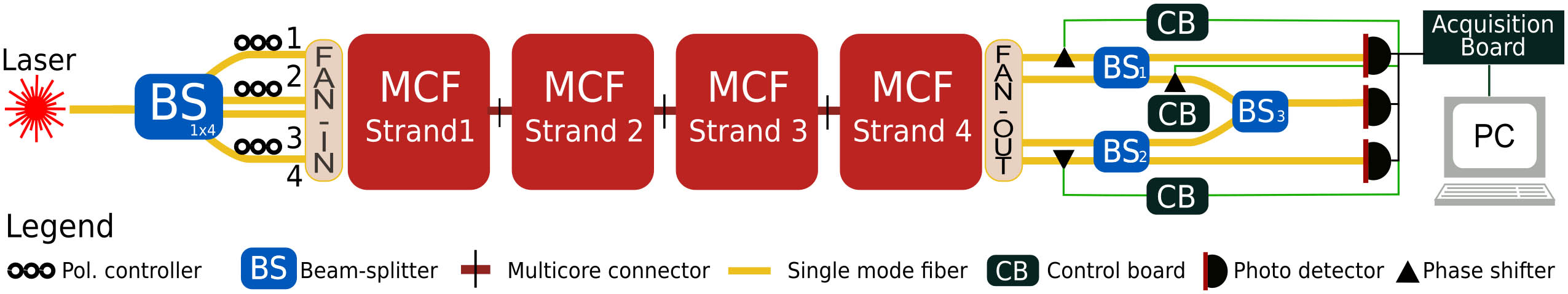
Figure 1.Experimental setup. A continuous wave laser at 1550 nm is equally divided into four paths through a
In order to fully and individually control the relative phases between the four uncoupled cores, a phase lock loop (PLL) has been integrated in each interferometer. The main component of each PLL is the control board (CB) composed by an ADuC7020 microcontroller unit (MCU) produced by Analog Devices. This device incorporates a five-channel 12 bit analog-to-digital converter (ADC) and a four-channel 12 bit digital-to-analog converter (DAC). Thanks to the high resolution of the analog channels and to the high computational power of the MCU, this microcontroller is suitable to implement a digital proportional-integral-derivative (PID) controller with the ability to efficiently stabilize the MCF interferometers. In order to maximize the computational power available to stabilize each interferometer, we used a dedicated ADuC7020 for each PLL. The feedback signal (FS) used by the PLL is a portion of the output of the photo-detector monitoring the same interfeometer the PLL is controlling. An ADC channel, preceded by a low-pass filter with a bandwidth of 1 kHz, is used to acquire this signal. The intensity of this signal can be related to the relative phase
![]()
Figure 2.Flow chart of the PID controller. This algorithm is used for controlling each phase shifter in the three different interferometers.
The PID block is divided into three main stages. The starting point is a serial input from the user that communicates the locking phase to the microcontroller, i.e., the phase where the interferometer should be locked. This command activates the first stage, where the voltage applied to the phase shifter is scanned in order to produce a phase variation slightly bigger than
3. RESULTS
In order to phase-stabilize the cores of the MCF, we built the three interferometers as described in the previous paragraph. The first parameter to be evaluated in these interferometers is the visibility, which is directly linked to the performance of a quantum or classical communication protocol, in terms of expected error rate. In Fig. 3(a), the red (blue) curve shows the interference fringes obtained by driving, with a triangular shape, the fiber phase shifter in the two-path interferometer involving cores 1 and 2 (3 and 4) of the MCF. These two interferometers, as shown in the experimental setup in Fig. 1, are independent. We measured a visibility of
![]()
Figure 3.Visibility fringes of the interferometers. (a) Interference signals as a function of time for the two independent interferometers between cores 1 and 2 and cores 3 and 4. Measured visibility of
Subsequent to the visibility measurement, we investigated the possibility of stabilizing the four different cores of the MCF for a certain amount of time. The stabilization of the relative phase between the cores of an MCF is an essential property for the reliable transmission of the quantum states, both in quantum key distribution applications and in more advanced quantum network protocols. We report in Fig. 4(a) the temporal drift of the relative phases between the cores, observed with the unlocked interferometers over a continuous and free-running acquisition of 10 min. Figure 4(b) shows the same acquisition, in which we have turned on the three automatic PLL systems to actively compensate the drifts. Both figures show the behavior of the interferometer in the four-strand configuration. In order to stabilize all of the different cores, we have first locked the two independent interferometers involving cores 1 and 2 and cores 3 and 4, and, subsequently, we have locked the overall interferometer. Note that, in case of fast and abrupt drifts in the fiber, i.e., when the locking position is suddenly lost, our PLL system is able to automatically re-lock to the same position by restarting the PLL algorithm from the first stage (see Fig. 2). The whole operation, required to re-lock the three interferometers, typically takes from 3 s to 10 s, which is a very short time compared to the stabilization time of 10 min reported in Fig. 4(b). Another important point to be highlighted is that the polarization of the different cores was stable over 100 min of acquisition time.
![]()
Figure 4.Phase drifts of the non-stabilized and stabilized four concatenated strands multicore interferometers over 10 min acquisition. (a) Phase drift between two-core and four-core interferometers without active phase stabilization. (b) Phase drift of (a) but with active phase stabilization loops. Different colors represent the three different configurations (red and blue, two-path interferometers; yellow, four-path interferometer).
In addition, we further investigated the free-running acquisition in order to better characterize the signal phase fluctuations in the MCF for different fiber lengths. To this end, we made additional 30 min acquisitions, with 6 Hz sampling rate, of the cores’ interference signals for multiple strands. In Fig. 5, we show the results of these measurements. In Fig. 5(a), we report the power spectrum of the interference signal as a function of frequency for one of the two-core interferometers (1 and 2). In Fig. 5(b), we report the same measurement for the four-core interferometer.
![]()
Figure 5.Frequency analysis of the interference signals. (a) Two-core intereferometers for the four different strands. (b) Four-core interferometer for the four different strands. Different colors represent different strands. Each measurement has been acquired for 30 min in the non-locked system.
4. DISCUSSION
Optical interferometers are the basic component for optical signal processing. More specifically, fiber-based interferometers are widely used for different applications, spanning from sensing and optical communication to quantum physics and gravitational wave detections. Multipath interferometers are used for manipulating quantum states and high-dimensional unitary operations, and, in this work, we demonstrated the possibility of stabilizing a long-distance MCF through a simple and scalable setup. For example, we might imagine using a wavelength multiplexing approach for transmitting quantum and classical light in the same fiber. One of these channels could be used for stabilizing the drift of the relative phase as demonstrated in Ref. [19]. In the same paper, we also propose a full setup of a four-dimensional quantum key distribution protocol exploiting different wavelengths for stabilizing the MCF. In the same direction, we have also demonstrated that the phase drift is not directly related to the length of the MCF. In fact, by looking at Fig. 5, both configurations seem quite insensitive to the overall interferometric size. This behavior can be explained by considering that most of the phase fluctuations come from the fibers connecting the rack-mount optical patch panel to the rest of the experimental setup and to the fiber components used to implement the interferometer itself, located on a table as close to it as possible. In other words, we can assume that the most unstable portion of the interferometric apparatus is not the MCF [24].
The second evidence, from Fig. 5(b), is that the four-core interferometer is more sensitive to phase fluctuations than the two-path configurations. In fact, the spectral density function of the four-core interferometer is about two orders of magnitude higher compared to the two-path one. This fact, as already demonstrated in Refs. [25–29], could be quite useful for sensing applications, both classical and quantum.
Note that in our demonstration we have used cascaded interferometers for analyzing independently all of the optical signals, but new devices have been recently introduced for a multi-port BS [30]. These devices are properly designed for acting as interfaces between single-mode fibers and MCFs and could increase the overall stability of the system. In the same direction, the scalability of the entire setup for larger dimensionality (more cores) is not straightforward by using bulk and fiber optics, since multiple locking stages are necessary for stabilizing a larger amount of cores. However, it has already been demonstrated that integrated photonics could help in accomplishing this task. As an example, our previous demonstration showed the possibility of manipulating and controlling quantum states using silicon photonics [13].
Summarizing, we presented here a scalable and efficient method for stabilizing the phase drifts in an MCF. The presented method can, in principle, be applied to longer fiber distances and larger core counts by using the same technology. Our demonstration paves the way towards future investigations and applications of MCFs in quantum communication [31].
References
[1] K. Saitoh, S. Matsuo. Multicore fiber technology. J. Lightwave Technol., 34, 55-66(2016).
[2] Y. Amma, Y. Sasaki, K. Takenaga, S. Matsuo, J. Tu, K. Saitoh, M. Koshiba, T. Morioka, Y. Miyamoto. “High-density multicore fiber with heterogeneous core arrangement. Optical Fiber Communications Conference and Exhibition (OFC), 1-3(2015).
[3] H. Hu, F. Da Ros, M. Pu, F. Ye, K. Ingerslev, E. P. da Silva, M. Nooruzzaman, Y. Amma, Y. Sasaki, T. Mizuno, Y. Miyamoto, L. Ottaviano, E. Semenova, D. Zibar, M. Galili, K. Yvind, T. Morioka, L. K. Oxenløwe. Single-source chip-based frequency comb enabling extreme parallel data transmission. Nat. Photonics, 12, 469-473(2018).
[4] T. Hayashi, T. Nagashima, T. Nakanishi, T. Morishima, R. Kawawada, A. Mecozzi, C. Antonelli. Field-deployed multi-core fiber testbed. 24th OptoElectronics and Communications Conference (OECC) and 2019 International Conference on Photonics in Switching and Computing (PSC), 1-3(2019).
[5] T. Hayashi, T. Taru, O. Shimakawa, T. Sasaki, E. Sasaoka. Low-crosstalk and low-loss multi-core fiber utilizing fiber bend. Optical Fiber Communication Conference, OWJ3(2011).
[6] T. Hayashi, Y. Tamura, T. Hasegawa, T. Taru. Record-low spatial mode dispersion and ultra-low loss coupled multi-core fiber for ultra-long-haul transmission. J. Lightwave Technol., 35, 450-457(2017).
[7] H. Yuan, M. Furdek, A. Muhammad, A. Saljoghei, L. Wosinska, G. Zervas. Space-division multiplexing in data center networks: on multi-core fiber solutions and crosstalk-suppressed resource allocation. J. Opt. Commun. Netw., 10, 272-288(2018).
[8] K. Abedin, T. Taunay, M. Fishteyn, D. DiGiovanni, V. Supradeepa, J. Fini, M. Yan, B. Zhu, E. Monberg, F. Dimarcello. Cladding-pumped erbium-doped multicore fiber amplifier. Opt. Express, 20, 20191-20200(2012).
[9] M. Nooruzzaman, T. Morioka. Multi-core fibers in submarine networks for high-capacity undersea transmission systems. Optical Fiber Communications Conference and Exhibition (OFC), 1-3(2017).
[10] J. Dynes, S. Kindness, S.-B. Tam, A. Plews, A. Sharpe, M. Lucamarini, B. Fröhlich, Z. Yuan, R. Penty, A. Shields. Quantum key distribution over multicore fiber. Opt. Express, 24, 8081-8087(2016).
[11] D. Bacco, B. Da Lio, D. Cozzolino, F. Da Ros, X. Guo, Y. Ding, Y. Sasaki, K. Aikawa, S. Miki, H. Terai, H. Terai, T. Yashimita, J. S. Neergaard-Nielsen, M. Galili, K. Rottwitt, U. A. Andersen, T. Morioka, L. K. Oxenløwe. Boosting the secret key rate in a shared quantum and classical fibre communication system. Commun. Phys., 2, 140(2019).
[12] B. Da Lio, D. Bacco, D. Cozzolino, F. Da Ros, X. Guo, Y. Ding, Y. Sasaki, K. Aikawa, S. Miki, H. Terai, T. Yashimita, J. S. Neergaard-Nielsen, M. Galili, K. Rottwitt, U. A. Andersen, L. K. Oxenløwe, T. Morioka. Record-high secret key rate for joint classical and quantum transmission over a 37-core fiber. IEEE Photonics Conference (IPC), 1-2(2018).
[13] Y. Ding, D. Bacco, K. Dalgaard, X. Cai, X. Zhou, K. Rottwitt, L. K. Oxenløwe. High-dimensional quantum key distribution based on multicore fiber using silicon photonic integrated circuits. npj Quantum Inf., 3, 25(2017).
[14] G. Cañas, N. Vera, J. Cariñe, P. González, J. Cardenas, P. Connolly, A. Przysiezna, E. Gómez, M. Figueroa, G. Vallone, P. Villoresi, T. Ferreira da Silva, G. B. Xavier, G. Lima. High-dimensional decoy-state quantum key distribution over multicore telecommunication fibers. Phys. Rev. A, 96, 022317(2017).
[15] D. Bacco, Y. Ding, K. Dalgaard, K. Rottwitt, L. K. Oxenløwe. Space division multiplexing chip-to-chip quantum key distribution. Sci. Rep., 7, 12459(2017).
[16] G. B. Xavier, G. Lima. Quantum information processing with space-division multiplexing optical fibres. Commun. Phys., 3, 9(2020).
[17] B. Da Lio, D. Bacco, D. Cozzolino, N. Biagi, T. N. Arge, E. Larsen, K. Rottwitt, Y. Ding, A. Zavatta, L. K. Oxenløwe. Stable transmission of high-dimensional quantum states over a 2-km multicore fiber. IEEE J. Sel. Top. Quantum Electron., 26, 6400108(2019).
[18] D. Cozzolino, B. Da Lio, D. Bacco, L. K. Oxenløwe. High-dimensional quantum communication: benefits, progress, and future challenges. Adv. Quantum Technol., 2, 1900038(2019).
[19] B. Da Lio, D. Cozzolino, B. Nicola, Y. Ding, K. Rottwitt, A. Zavatta, D. Bacco, L. K. Oxenløwe. Path-encoded high-dimensional quantum communication over a 2 km multicore fiber. npj Quantum Inf., 7, 63(2021).
[20] A. Alarcón, J. Argillander, G. Lima, G. B. Xavier. Few-mode fibre technology fine-tunes losses of quantum communication systems.
[21] R. S. Luís, B. J. Puttnam, G. Rademacher, A. Marotta, C. Antonelli, F. Graziosi, A. Mecozzi, T. Hayashi, T. Nakanishi, S. Shinada, Y. Awaji, H. Furukawa, N. Wada. Evaluation of dynamic skew on spooled and deployed multicore fibers using O-band signals. Optical Fiber Communications Conference and Exhibition (OFC), T4J.4(2020).
[22] B. J. Puttnam, R. S. Luis, G. Rademacher, A. Marotta, C. Antonelli, A. Mecozzi, F. Graziosi, T. Hayashi, T. Nakanishi, Y. Awaji, H. Furukawa, N. Wada. Dynamic skew measurements in a deployed 4-core fiber. Conference on Lasers and Electro-Optics, STu4R.1(2020).
[23] L. Rozsa. Design and implementation of practical digital PID controllers. IFAC Proc. Vol., 22, 115-121(1989).
[24] X.-M. Hu, W.-B. Xing, B.-H. Liu, D.-Y. He, H. Cao, Y. Guo, C. Zhang, H. Zhang, Y.-F. Huang, C.-F. Li, G.-C. Guo. Efficient distribution of high-dimensional entanglement through 11 km fiber. Optica, 7, 738-743(2020).
[25] Z. Zhao, Z. Liu, M. Tang, S. Fu, L. Wang, N. Guo, C. Jin, H.-Y. Tam, C. Lu. Robust in-fiber spatial interferometer using multicore fiber for vibration detection. Opt. Express, 26, 29629-29637(2018).
[26] G. M. D’Ariano, M. G. Paris. Arbitrary precision in multipath interferometry. Phys. Rev. A, 55, 2267-2271(1997).
[27] L. Gan, R. Wang, D. Liu, L. Duan, S. Liu, S. Fu, B. Li, Z. Feng, H. Wei, W. Tong, P. Shum, M. Tang. Spatial-division multiplexed Mach–Zehnder interferometers in heterogeneous multicore fiber for multiparameter measurement. IEEE Photon. J., 8, 7800908(2016).
[28] K. U. Schreiber, J.-P. R. Wells. Invited review article: large ring lasers for rotation sensing. Rev. Sci. Instrum., 84, 041101(2013).
[29] G. Weihs, M. Reck, H. Weinfurter, A. Zeilinger. All-fiber three-path Mach–Zehnder interferometer. Opt. Lett., 21, 302-304(1996).
[30] L. Pereira, A. Rojas, G. Cañas, G. Lima, A. Delgado, A. Cabello. Universal multi-port interferometers with minimal optical depth(2020).
[31] D. Bacco, J. F. Bulmer, M. Erhard, M. Huber, S. Paesani. A proposal for practical multidimensional quantum networks(2021).


Set citation alerts for the article
Please enter your email address

© Copyright 2018-2021 | Chinese Laser Press. All Rights Reserved 沪ICP备15018463号-20