• Opto-Electronic Advances
  • Vol. 6, Issue 4, 220063 (2023)
Dongliang Tang1、†,*, Zhenglong Shao1、†, Xin Xie2、†,**, Yingjie Zhou1, Xiaohu Zhang3, Fan Fan1、***, and Shuangchun Wen1
Author Affiliations
  • 1Key Laboratory for Micro/Nano Optoelectronic Devices of Ministry of Education & Hunan Provincial Key Laboratory of Low-Dimensional Structural Physics and Devices, School of Physics and Electronics, Hunan University, Changsha 410082, China
  • 2Key Laboratory of Light Field Manipulation and Information Acquisition, Ministry of Industry and Information Technology, and Shaanxi Key Laboratory of Optical Information Technology, School of Physical Science and Technology, Northwestern Polytechnical University, Xi’an 710129, China
  • 3Key Laboratory of Optoelectronic Technology and Systems of the Education Ministry of China, Chongqing University, Chongqing 400044, China
  • show less
    DOI: 10.29026/oea.2023.220063 Cite this Article
    Dongliang Tang, Zhenglong Shao, Xin Xie, Yingjie Zhou, Xiaohu Zhang, Fan Fan, Shuangchun Wen. Flat multifunctional liquid crystal elements through multi-dimensional information multiplexing[J]. Opto-Electronic Advances, 2023, 6(4): 220063 Copy Citation Text show less
    Principle of a multifunctional LC element utilizing the incident polarization, observation position and working wavelength to decode their associated information. Information multiplexing FMLCE generates a pattern at the sample surface under an orthogonal-polarization optical path, and different holographic images in Fresnel region depending on the incident polarization state (polarization channel), observation position (space channel), and working wavelength (wavelength channel).
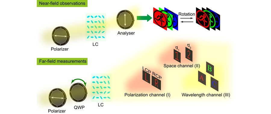
    Fig. 1. Principle of a multifunctional LC element utilizing the incident polarization, observation position and working wavelength to decode their associated information. Information multiplexing FMLCE generates a pattern at the sample surface under an orthogonal-polarization optical path, and different holographic images in Fresnel region depending on the incident polarization state (polarization channel), observation position (space channel), and working wavelength (wavelength channel).
    Flowchart of designing a multifunctional LC element for simultaneous near-field display and far-field holography. (a) Schematic of the anisotropic LC molecule. (b) Normalized transmitted intensity follows the relation of sin2(2θ) under an orthogonal-polarization optical path. (c) Phase of the transmitted component follows the linear relation of 2θ or −2θ when LCP or RCP illumination is converted to its cross-polarized light. (d) LC orientation has four options for an equal intensity under an orthogonal-polarization optical path but provides different geometric phase shifts under LCP and RCP illumination. With the powerful GA optimization to compare the difference between the possible holographic image and target far-field image, a suitable LC orientation arrangement can be obtained. Target far-field images can be chosen with various polarization, position and wavelength information.
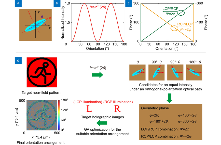
    Fig. 2. Flowchart of designing a multifunctional LC element for simultaneous near-field display and far-field holography. (a) Schematic of the anisotropic LC molecule. (b) Normalized transmitted intensity follows the relation of sin2(2θ) under an orthogonal-polarization optical path. (c) Phase of the transmitted component follows the linear relation of 2θ or −2θ when LCP or RCP illumination is converted to its cross-polarized light. (d) LC orientation has four options for an equal intensity under an orthogonal-polarization optical path but provides different geometric phase shifts under LCP and RCP illumination. With the powerful GA optimization to compare the difference between the possible holographic image and target far-field image, a suitable LC orientation arrangement can be obtained. Target far-field images can be chosen with various polarization, position and wavelength information.
    Experimental results of the polarization multiplexing LC element. (a) Home-built experimental setups for near-field and far-field measurements. (b) Measured results of FMLCE A at the wavelengths of 638 nm, 520 nm and 445 nm, respectively. The element can generate a near-field pattern (and its complementary pattern) under an orthogonal-polarization optical setup, and two different far-field holographic images under LCP and RCP illuminations. Scalar bars are 300 μm.
    Fig. 3. Experimental results of the polarization multiplexing LC element. (a) Home-built experimental setups for near-field and far-field measurements. (b) Measured results of FMLCE A at the wavelengths of 638 nm, 520 nm and 445 nm, respectively. The element can generate a near-field pattern (and its complementary pattern) under an orthogonal-polarization optical setup, and two different far-field holographic images under LCP and RCP illuminations. Scalar bars are 300 μm.
    Experimental results of the space multiplexing FMLCE B at the wavelengths of 638 nm, 520 nm and 445 nm. It can generate a near-field pattern under an orthogonal-polarization optical setup, and two far-field holographic images at two different space positions under circular polarized illuminations. Scalar bars are 300 μm.
    Fig. 4. Experimental results of the space multiplexing FMLCE B at the wavelengths of 638 nm, 520 nm and 445 nm. It can generate a near-field pattern under an orthogonal-polarization optical setup, and two far-field holographic images at two different space positions under circular polarized illuminations. Scalar bars are 300 μm.
    Simulated and experimental results of the wavelength multiplexing LC element. (a–d) represent the simulation results and (e–h) represent the experimental results. FMLCE C generates (a, e) a near-field pattern under an orthogonal-polarization optical path and far-field holographic images containing, (b, f) an English alphabet of “A” under red LCP illumination, (c, g) an English alphabet of “B” under green LCP illumination, and (d, h) an English alphabet of “C” under blue LCP illumination. Three holographic images are observed at the same plane. The polarizer and analyzer are orthogonal and indicated by double-ended arrows. Scalar bars are 300 μm.
    Fig. 5. Simulated and experimental results of the wavelength multiplexing LC element. (ad) represent the simulation results and (eh) represent the experimental results. FMLCE C generates (a, e) a near-field pattern under an orthogonal-polarization optical path and far-field holographic images containing, (b, f) an English alphabet of “A” under red LCP illumination, (c, g) an English alphabet of “B” under green LCP illumination, and (d, h) an English alphabet of “C” under blue LCP illumination. Three holographic images are observed at the same plane. The polarizer and analyzer are orthogonal and indicated by double-ended arrows. Scalar bars are 300 μm.
    Dongliang Tang, Zhenglong Shao, Xin Xie, Yingjie Zhou, Xiaohu Zhang, Fan Fan, Shuangchun Wen. Flat multifunctional liquid crystal elements through multi-dimensional information multiplexing[J]. Opto-Electronic Advances, 2023, 6(4): 220063
    Download Citation