1Key Laboratory for Micro/Nano Optoelectronic Devices of Ministry of Education & Hunan Provincial Key Laboratory of Low-Dimensional Structural Physics and Devices, School of Physics and Electronics, Hunan University, Changsha 410082, China
2Key Laboratory of Light Field Manipulation and Information Acquisition, Ministry of Industry and Information Technology, and Shaanxi Key Laboratory of Optical Information Technology, School of Physical Science and Technology, Northwestern Polytechnical University, Xi’an 710129, China
3Key Laboratory of Optoelectronic Technology and Systems of the Education Ministry of China, Chongqing University, Chongqing 400044, China
Flat optical elements have attracted enormous attentions and act as promising candidates for the next generation of optical components. As one of the most outstanding representatives, liquid crystal (LC) has been widely applied in flat panel display industries and inspires the wavefront modulation with the development of LC alignment techniques. However, most LC elements perform only one type of optical manipulation and are difficult to realize the multifunctionality and light integration. Here, flat multifunctional liquid crystal elements (FMLCEs), merely composed of anisotropic LC molecules with space-variant orientations, are presented for multichannel information manipulation by means of polarization, space and wavelength multiplexing. Specifically, benefiting from the unique light response with the change of the incident polarization, observation plane, and working wavelength, a series of FMLCEs are demonstrated to achieve distinct near- and far-field display functions. The proposed strategy takes full advantage of basic optical parameters as the decrypted keys to improve the information capacity and security, and we expect it to find potential applications in information encryption, optical anti-counterfeiting, virtual/augmented reality, etc.
Introduction
The integration and miniaturization of optical systems is at the mainstream of current research works in modern optics and beneficial in various scientific communities such as physics, chemistry, biology, and medicine. Conventional refractive optical elements including planoconvex/doublet lenses and waveplates shape the incident wavefront through controlling light propagation in the media with different thicknesses1-3. Large volumes of these elements limit the development of a compact and lightweight optical system, especially for a high numerical aperture system, where a larger light bending angle is required. Compared with the refractive optics, diffractive optics works through exploiting the interference of the transmissive or refractive light4-6. Diffractive optical elements (DOEs) with appropriate amplitude or phase masks can be utilized for beam shaping, such as blazed gratings, Fresnel lenses, and beam homogenizer. Generally, higher diffraction orders should be properly considered in DOE design because they cause a low energy efficiency. In recent years, with the development of nano-fabrication technology, metasurfaces are proposed to reduce the thicknesses and volumes of optical elements7-25. The light modulation introduced by metasurfaces depends on a totally different approach from the traditional methodology: artificially engineered subwavelength resonators are designed to introduce abrupt light responses at the interface. A series of novel metasurfaces have been demonstrated to control phase, amplitude and polarization of light, such as focusing lenses, beam deflectors, waveplates, vortex beam generators, holographic plates, etc8-24.
Similar to metasurfaces by imparting the abrupt phase shift at the interface, liquid crystal (LC) molecules with spatially variant orientations can be used to generate desired phase profiles based on the Pancharatnam-Berry (PB) geometric phase26-34. A range of photoalignment techniques with high fabrication resolution have also been developed to precisely control the orientations of LC molecules35-37, and the half-wave condition can be realized by controlling the thickness of LC layer to achieve a high polarization conversion efficiency, which is up to 100% at the designed wavelength. High-performance focusing lenses, polarization gratings, non-diffraction Airy beam generators, and holograms have been experimentally demonstrated27, 31, 33, 38, and the size of PB-based LC element can be up to few millimeters, which can be easily integrated in current optical systems. Furthermore, commercial LC displays have been successfully fabricated with mature production lines and widely applied in our daily life, such as smartphones, desktop computers and TVs. These parallel techniques promise various LC applications ranging from optical displayers to functional light modulators, and make LC elements particularly attractive. However, most of LC elements can perform only one type of optical manipulation and therefore have limited functions. It is urgent to develop multifunctional LC elements with the capability to simultaneously realize more than two types of optical manipulations for the increase of the device multifunctionality and light integration.
Here, flat multifunctional LC elements (FMLCEs) composed of space-variant LC molecules are proposed for simultaneous near-field displayers and far-field holograms. The specific working conditions, such as incident polarization state, observation plane and working wavelength, play essential and independent parameters to encode and decode their associated information. Utilizing the polarization, space and wavelength multiplexing technologies, three FMLCEs are designed and experimentally measured to verify the decoupled near- and far-field functions. We anticipate that our proposed FMLCEs with low cost and high integration can stimulate the development of image display, optical information storage, information multiplexing and AR/VR intelligence.
Results
Principle for designing an information multiplexing FMLCE
In classical optics, diffraction always arises in light propagation. Various analytical models have been proposed to calculate the diffraction field, such as Huygens–Fresnel principle39, 40. This theory was further developed and denoted as Kirchhoff–Fresnel diffraction. Based on different approximation of the Kirchhoff–Fresnel diffraction, Fresnel and Fraunhofer diffraction are well-known to calculate the near- and far-field light distribution, respectively. To take a closer look at the model of light propagation and suppose the light field at z = 0 is U0(x, y; 0), the light distribution of Ud(x, y; d) over a propagation distance z = d can be calculated as:
where FT represents the two-dimensional Fourier transform; H(fx, fy) represents the transfer function and can be calculated using Eq. (S1); fx and fy are the frequency components along x and y directions (fx= x/λ/d, fy= y/λ/d). It is easily seen from Eq. (1) that the light distribution Ud(x,y; d) is related to the working wavelength (λ) and observation position (d), which can act as the keys to code and decode their related information. Besides, since the anisotropic structures have a polarization-sensitive light distribution U0(x,y; 0), the incident polarization state can also serve as a key to code different information.
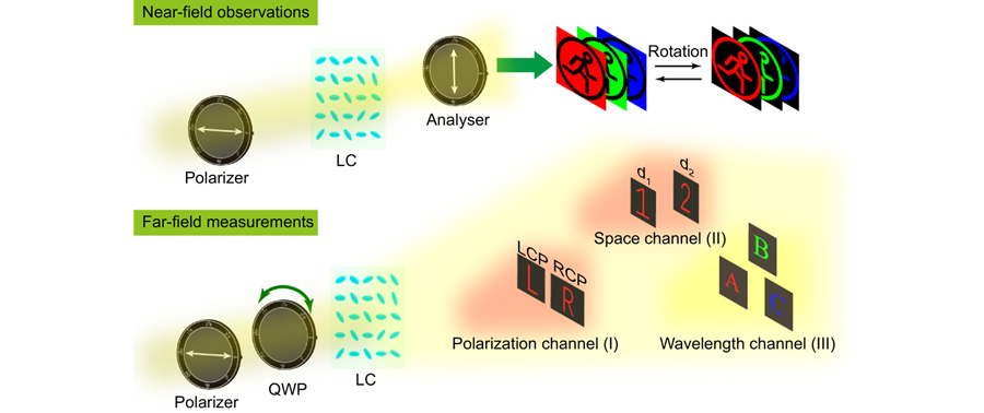
Therefore, multifunctional elements can be constructed by merging these kinds of independent information (i.e., incident polarization, observation position and working wavelength) together. As a proof of concept, several FMLCEs are designed to show multi-channel image displays. As shown in Fig. 1, each FMLCE can generate a pattern and its complementary image at the sample surface when it is inserted into an orthogonal-polarization optical path (the path contains a polarizer and an analyzer, and the polarization direction of the analyzer is orthogonal to that of the polarizer). At the same time, the elements can project different holographic images in the far field depending on the incident polarization state (polarization channel), observation position (space channel), and working wavelength (wavelength channel).
Figure 1.Principle of a multifunctional LC element utilizing the incident polarization, observation position and working wavelength to decode their associated information. Information multiplexing FMLCE generates a pattern at the sample surface under an orthogonal-polarization optical path, and different holographic images in Fresnel region depending on the incident polarization state (polarization channel), observation position (space channel), and working wavelength (wavelength channel).
The light modulation of anisotropic LC molecule (Fig. 2(a)) is analyzed by using the Jones matrix formalism (see Supplementary information Section 2)41, 42. If LC is inserted into the orthogonal-polarization optical path, the normalized transmitted intensity follows the relation of sin2(2θ) (Fig. 2(b)), where θ is the orientation angle between the long axis of the LC molecule and x axis. Therefore, the amplitude modulation at the sample surface can be easily achieved by rotating the LC molecule. Meanwhile, according to the PB phase theory, when the left-hand circular polarized (LCP) or right-hand circular polarized (RCP) light illuminates on LC, the output cross-polarized light will be imprinted with a geometric phase equal to exp(i2θ) or exp(–i2θ) (Fig. 2(c)). The duality of the light modulation provides an approach to multiplex polarization-related information into a single piece of LC element.
Figure 2.Flowchart of designing a multifunctional LC element for simultaneous near-field display and far-field holography. (a) Schematic of the anisotropic LC molecule. (b) Normalized transmitted intensity follows the relation of sin2(2θ) under an orthogonal-polarization optical path. (c) Phase of the transmitted component follows the linear relation of 2θ or −2θ when LCP or RCP illumination is converted to its cross-polarized light. (d) LC orientation has four options for an equal intensity under an orthogonal-polarization optical path but provides different geometric phase shifts under LCP and RCP illumination. With the powerful GA optimization to compare the difference between the possible holographic image and target far-field image, a suitable LC orientation arrangement can be obtained. Target far-field images can be chosen with various polarization, position and wavelength information.
Figure 2(d) shows the design strategy to arrange the LC orientations. Specifically, once the target pattern at the sample surface is determined, there are four orientation candidates as θ, 90°–θ, 90°+θ and 180°–θ at each pixel for an identical intensity under an orthogonal-polarization optical path. For example, there are four orientation choices (θ= 15°, 75°, 105° and 165°) to generate the intensity of 0.25. The phenomenon is also known as the orientation degeneracy42-45, and the orientation degeneracy value of M here is 4. At the same time, one can obtain the geometric phase shifts of 2θ, 180°–2θ, 180°+2θ, and 360°–2θ under LCP incidence, and –(2θ), –(180°–2θ), –(180°+2θ), and –(360°–2θ) under RCP incidence. If the total number of LC pixels is N, possible combinations of LC orientations to generate different geometric phase profiles under LCP or RCP light are MN. Next, genetic algorithm (GA) is utilized to optimize the arrangement of LC orientations through comparing the difference between each possible holographic image and the target far-field image (see Supplementary information Section 3).
Experimental demonstration
To verify our proposed methodology, three FMLCEs for polarization, space and wavelength multiplexing are respectively designed. All the elements have a size of 2.7×2.7 mm2 (500×500 pixels), and are fabricated through a standard photoalignment technology and a digital micro-mirror device (DMD). Details of the fabrication and measurement process can be found in Experimental section.
Polarization-multiplexing FMLCE A generates a pattern at the sample surface when it is inset into the orthogonal-polarization optical path for red light (638 nm), as shown in Fig. 3(a) and 3(b). After rotating the sample by 45°, a complementary pattern is generated. It is easy to understand that the normalized intensity of the cross-polarized component changes from sin2(2θ) to cos2(2θ), and the black and white pattern at the sample surface would be reversed. We remove the analyzer and add a quarter-wave plate (QWP) behind the polarizer to observe the far-field holographic image. Two English alphabets (“L” and “R”) are clearly observed at d = 100 mm under the LCP and RCP illuminations. In the design, these two holographic images for LCP and RCP incidence are simultaneously set as the target functions in our optimization. A straightforward insight can be found from the interleaving design strategy, where some regions have the responses under LCP incidence while others have the responses under RCP incidence. However, these regions of our element corresponding to LCP or RCP incidence are not easy to distinguish because the LC orientation at each pixel is determined by GA with a global optimization. The experimental results indicate that our element works well with both intensity and phase modulation. As the light modulation of the LC molecule is independent of the wavelength (as calculated through Eqs. (S4) and (S5)), our element can operate under other wavelengths. To investigate the broadband response, near-field patterns and far-field holographic images are measured under the illumination of the green (520 nm) and blue (445 nm) light. The sizes of holographic images are almost the same at the three wavelengths. However, the holographic images are formed at a shifted plane because of the chromatic aberration in the air propagation, and the observation plane is at 127 mm for 520 nm and 144 mm for 445 nm. The distance between the observation plane and sample plane follow a reciprocal relation with the working wavelength, and the product between these two values is nearly a constant. The broadband response of our proposed LC element can greatly reduce the limitation of the working condition in practical applications.
Figure 3.Experimental results of the polarization multiplexing LC element. (a) Home-built experimental setups for near-field and far-field measurements. (b) Measured results of FMLCE A at the wavelengths of 638 nm, 520 nm and 445 nm, respectively. The element can generate a near-field pattern (and its complementary pattern) under an orthogonal-polarization optical setup, and two different far-field holographic images under LCP and RCP illuminations. Scalar bars are 300 μm.
In our daily life, a flat device such as a common liquid crystal display only displays a pattern at the surface. Herein, a near-field pattern and a holographic image can be encoded into a single piece of LC element with high integration for a specific visual sense and multi-purpose display. For instance, an observer who has vision problems must wear glasses to capture the near-field display. To solve the problem, an element can be designed to generate the same image at the surface and far-field region (details can be found in Supplementary information Section 4). Following the same fabrication and measurement procedure, the near-field and far-field images containing same Chinese abbreviations of “University” are captured with high fidelity. Although the size of the near-field pattern is different from that of the holographic image, one can arbitrarily control their difference through choosing appropriate target images in optimization. Besides, it is a potential candidate in AR displays, i.e., a far-field holographic image can be mixed into the real-world scene where the near-field pattern is located.
It is also noted that a grayscale near-field pattern is possible in principle but there exist some disturbances among adjacent LC molecules because of the intermolecular force and fabrication precision (details are presented in Supplementary information Section 5). The polarization conversion efficiencies (PCEs) and holographic efficiencies are calculated and summarized in Supplementary information Section 6. PCEs are measured with 47.3%, 83.7% and 97.1% at 445 nm, 520 nm, and 638 nm, respectively. Also, the holographic efficiency changes with the working wavelength and is highest at 638 nm. As an example, the measured holographic efficiencies of FMLCE A under LCP light are 1.6%, 2.7% and 3.4% at the wavelengths of 445 nm, 520 nm, and 638 nm, respectively. There are some reasons for the low efficiency: a) the multiplexing strategy is used and we only measured the efficiency under LCP incidence; b) the phase level for the far-field holographic image is limited; c) some energy losses also exist in GA optimization, as the holographic efficiency is not set as the target function in the iteration process.
In the following, space-multiplexing FMLCE B is designed to simultaneously generate a near-field pattern and two far-field holographic images at different propagating distances. Specifically, it forms a binary gray pattern at the sample surface under an orthogonal-polarization optical path, an Arabic numeral “1” at d1 = 100 mm under LCP incidence and another Arabic numeral “2” at d2 = 150 mm under RCP illumination. The experimental results under red (638 nm), green (520 nm) and blue (445 nm) light are shown in Fig. 4. Note that more position information can be encoded into the element through more elaborate optimization. If FMLCE B is applied in optical encryption, the optical setup, incident polarization and observation plane can be considered as the special decrypted keys while the near- and far-field images as encrypted information carriers. Independent information channels associated with the specific working condition enable our element to have high fraudulence and security. Therefore, the space multiplexing methodology can greatly enhance the information density and security.
Figure 4.Experimental results of the space multiplexing FMLCE B at the wavelengths of 638 nm, 520 nm and 445 nm. It can generate a near-field pattern under an orthogonal-polarization optical setup, and two far-field holographic images at two different space positions under circular polarized illuminations. Scalar bars are 300 μm.
In the above measurements, there is a shift of the observation plane with the change of the incident wavelength. The main reason is that the chromatic aberration in the air propagation is not corrected2, though our FMLCEs provide a same geometric phase modulation without considering the material dispersion. In other words, only a single wavelength is corrected and considered in our design. To solve the problem, we propose a new design through simultaneously optimizing multiple working wavelengths for the correction of the chromatic aberration. The wavelength multiplexing FMLCE C generates a near-field pattern under an orthogonal-polarization optical path, at the same time, the English alphabet of “A” under red (638 nm) LCP illumination, “B” under green (520 nm) LCP illumination, and “C” under blue (445 nm) LCP illumination are observed at the plane of d = 100 mm, respectively. All the results are shown in Fig. 5 and agree well with the target images. In addition, the RCP illumination and observation position can be added into the optimization through the same design strategy with FMLCE A and B for the improvement of device functionalities.
Figure 5.Simulated and experimental results of the wavelength multiplexing LC element. (a–d) represent the simulation results and (e–h) represent the experimental results. FMLCE C generates (a, e) a near-field pattern under an orthogonal-polarization optical path and far-field holographic images containing, (b, f) an English alphabet of “A” under red LCP illumination, (c, g) an English alphabet of “B” under green LCP illumination, and (d, h) an English alphabet of “C” under blue LCP illumination. Three holographic images are observed at the same plane. The polarizer and analyzer are orthogonal and indicated by double-ended arrows. Scalar bars are 300 μm.
The information multiplexing technique proposed here can be applied in applications of optical anti-counterfeiting and encryption. Specifically, the orthogonal-polarization optical path, polarization state, observation position and working wavelength are regarded as security keys. The correct near-field pattern can be decrypted only when the sample is inserted in the orthogonal-polarization optical path (the rotation angle of the sample may also act as an additional security key, as reported in previous reference46), and far-field holographic images can be observed when the incident polarization state, observation plane and working wavelength are correct. Compared with the Malus-law-assisted metasurfaces42-44, where the holographic images were designed in the Fraunhofer region, our holographic images are formed in the Fresnel region without the twin image at the observation plane, and the distance between the observation plane and sample surface can be arbitrarily adjusted, thereby providing the degree of freedom in the design to improve the information capability.
Also, the orientation degeneracy is not only existed in the LC molecule. Any material with the anisotropic property can provide the possibility to control the light through the change of the polarization state. Malus-law-assisted metasurfaces have been proposed and experimentally demonstrated through the anisotropic metallic or low-loss dielectric nano-structures42-44. The subwavelength size of each modulator can provide a high pixel resolution. However, the precise control of the subwavelength resonator in metasurface in turn leads to the difficulty of the nano-fabrication and a small overall size. As for the LC element, there are no great barriers to fabricate low-cost LC elements as large-scale production lines of LC panels have been successfully operated and some photoalignment technologies have also been developed. In addition, the LC elements have the tunable property and can be used for the dynamic optical field modulation (our tunable results are presented in Supplementary information Section 9)47. Therefore, for the LC-based element and metasurface, each has its own advantages and one can choose any one depending on the application scenes, and they can inspire each other in structural design.
In summary, multifunctional LC elements through multi-dimensional information multiplexing technology are proposed for near-field displays and far-field holograms. The specific optical parameters including incident polarization state, observation plane and working wavelength act as key roles in the light response. By effectively combining the amplitude and phase modulation, a series of FMLCEs through polarization, space and wavelength multiplexing display different near- and far-field images with a change of the working condition. The design strategy can significantly improve the information capacity and density with less crosstalk. The proposed elements with multifunctionality, low-cost and large fabrication area are expected to empower advanced applications in the information multiplexing, optical anti-counterfeiting, optical displays and so on.
Experimental section
Sample fabrication: FMLCEs are fabricated based on a standard photoalignment technology using a DMD. The whole fabrication process is presented as follows: a) the glass substrate with the thickness of 1.1 mm is ultrasonically cleaned, adequately heated, UV-light exposed and compressed air blown; b) the solution mixed by the sulphonic azo-dye (SD1, 0.5%) and dimethylformamide (DMF, 99.5%) is dripped on the glass substrate, then spun for the even distribution and formation of the alignment layer; c) different patterns generated by DMD under various linear-polarized illumination are used to ensure photoalignment orientations of SD1; d) the solution of LC materials (OS1C-H1 from XAGIC Co., Ltd.) is spun on the SD1 orientation layer, then the LC orientations follow the SD1 orientations through intermolecular interactions. Herein, the thickness of the LC film can be adjusted to achieve the half-wave condition at the wavelength of 638 nm for a high cross-polarization conversion efficiency, i.e., making tu=1 and tv=−1 in Eq. (S2); e) the LC element is then polymerized for solidify by exposing it under the unpolarized light at 365 nm.
Experimental measurement: The schematic of our home-built optical measurement setup is shown in Fig. 3(a), where contains the laser with different wavelengths of 445 nm, 520 nm and 638 nm, an optical collimator, a linear polarizer (LP1), LC sample, an analyzer (LP2), and a colorful CCD with a magnified lens. When the laser beam is incident on a pinhole with diameter of 50 μm at the front focal plane of the collimator, the parallel beam would be formed behind the collimator. Our LC sample is mounted on a three-dimensional translation platform, which can be easy for the distance adjustment, and the colorful CCD with the magnified lens is fixed to capture the near-field pattern and holographic image through moving the sample. In near-field tests, our sample is inserted between the polarizer and analyzer, and the polarization state of the analyzer is orthogonal to that of the linear polarizer (i.e., the orthogonal-polarization optical path). In far-field tests, the analyzer is removed and a QWP is added behind the polarizer. LCP and RCP lights can be respectively generated through rotating the QWP.
References
[39] Born M, Wolf E. Principles of Optics: Electromagnetic Theory of Propagation, Interference and Diffraction of Light (Pergamon Press, London, 1959).
[40] Goodman JW. Introduction to Fourier Optics 3rd ed (Roberts & Company Publishers, Greenwoood Village, 2005).
[41] Zhang F, Xie X, Pu MB, Guo YH, Ma XL et al. Multistate switching of photonic angular momentum coupling in phase-change metadevices. Adv Mater32, 1908194 (2020).