
Xizheng Ke, Yanchen Xie, Ying Zhang. Orbital Angular Momentum Measurement of Vortex Beam and Its Performance Improvement[J]. Acta Optica Sinica, 2019, 39(1): 0126017
- Acta Optica Sinica
- Vol. 39, Issue 1, 0126017 (2019)
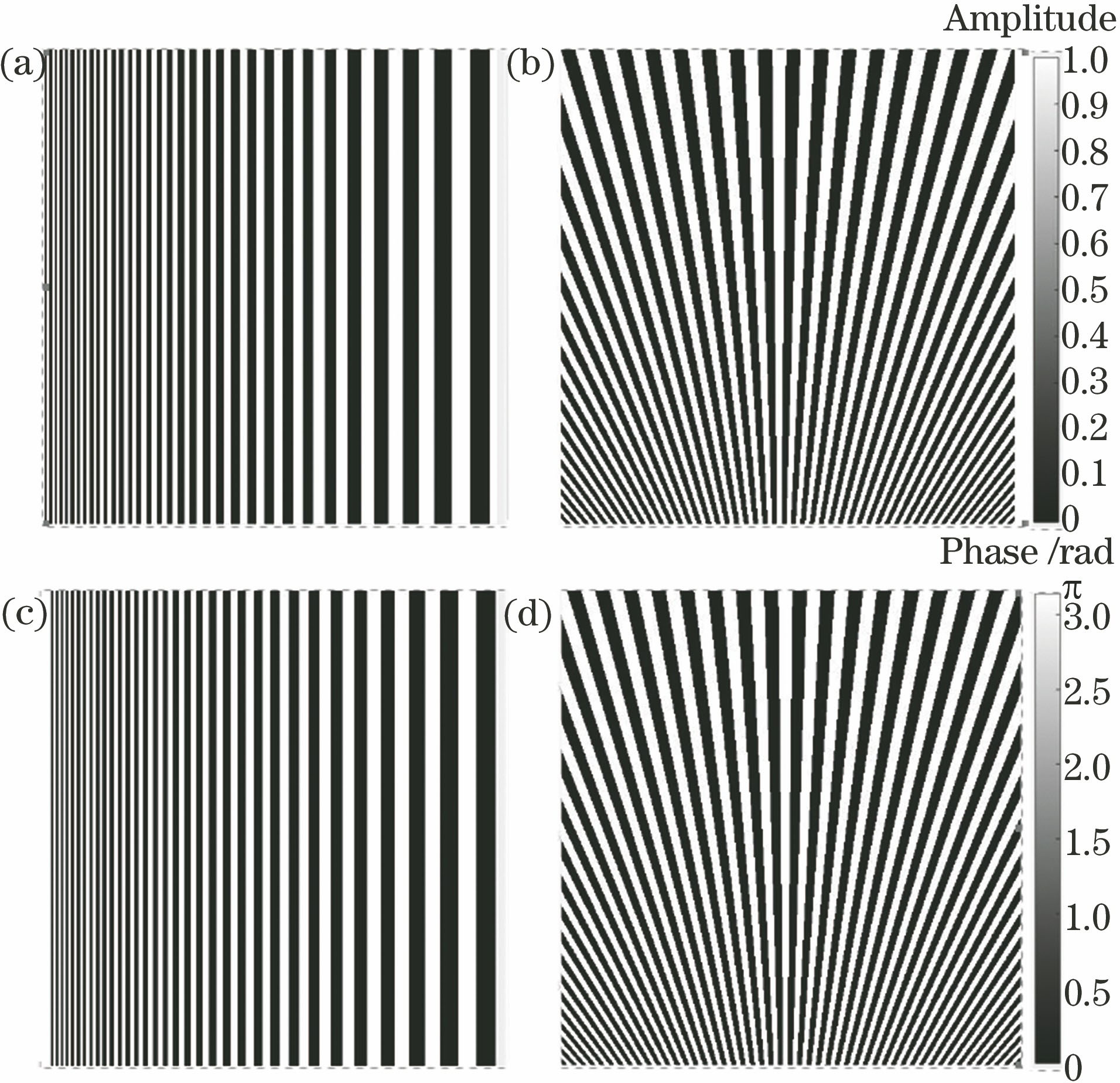
Fig. 1. (a) a-type and (b)b-type period-gradually-changing amplitude gratings; (c) a -type and (d)b-type 0-π binary period-gradually-changing phase gratings
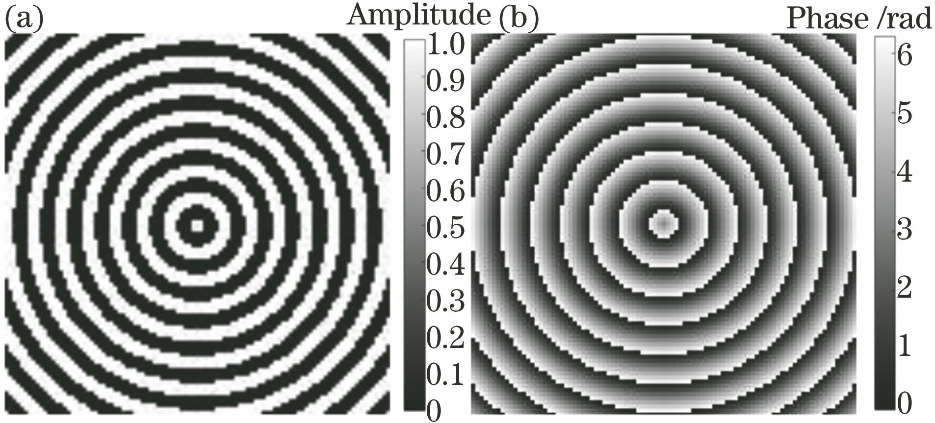
Fig. 2. (a) Annular amplitude grating; (b) annular phase grating
Fig. 3. Schematic of vortex beam diffraction by gratings. (a) Vortex beam; (b) grating; (c) diffraction patterns
Fig. 4. Phase profile diagram of phase-corrected optical element
Fig. 5. Fan-out phase images under different number of copies. (a) 7 times; (b) 9 times
Fig. 6. Simulation results for four period-gradually-changing gratings. (a)-(d) a-type period-gradually-changing amplitude gratings; (e)-(h) a-type 0-π binary period-gradually-changing phase gratings; (i)-(l) b-type period-gradually-changing amplitude gratings; (m)-(p) a-type 0-π binary period-gradually-changing phase gratings
Fig. 7. Simulation results for two annular gratings. (a)-(d) Annular amplitude gratings; (e)-(h) annular phase gratings
Fig. 8. Experimental setup
Fig. 9. Experimental results of detection and correction for four period-gradually-changing gratings. (a)-(d) a-type period-gradually-changing amplitude gratings; (e)-(h) a-type 0-π binary period-gradually-changing phase gratings; (i)-(l) b-type period-gradually-changing amplitude gratings; (m)-(p) b-type 0-π binary period-gradually-changing phase gratings
Fig. 10. Experimental results of detection and correction for two annular gratings. (a)-(d) Annular amplitude gratings; (e)-(h) annular phase gratings

Set citation alerts for the article
Please enter your email address
© Copyright 2018-2021 | Chinese Laser Press. All Rights Reserved 沪ICP备15018463号-20