• Acta Optica Sinica
  • Vol. 41, Issue 12, 1206001 (2021)
Jiuhang Nan1 and Yiping Han2、*
Author Affiliations
  • 1School of Communication Engineering, Xidian University, Xi'an, Shaanxi 710071, China
  • 2Department of Applied Physics, School of Physics and Optoelectronic Engineering, Xidian University, Xi'an, Shaanxi 710071, China
  • show less
    DOI: 10.3788/AOS202141.1206001 Cite this Article Set citation alerts
    Jiuhang Nan, Yiping Han. Dual-Channel Multiband Vortex Optical Communication[J]. Acta Optica Sinica, 2021, 41(12): 1206001 Copy Citation Text show less
    Phase and intensity of Laguerre-Gaussian beams with p=1 and m=3. (a) Phase; (b) intensity
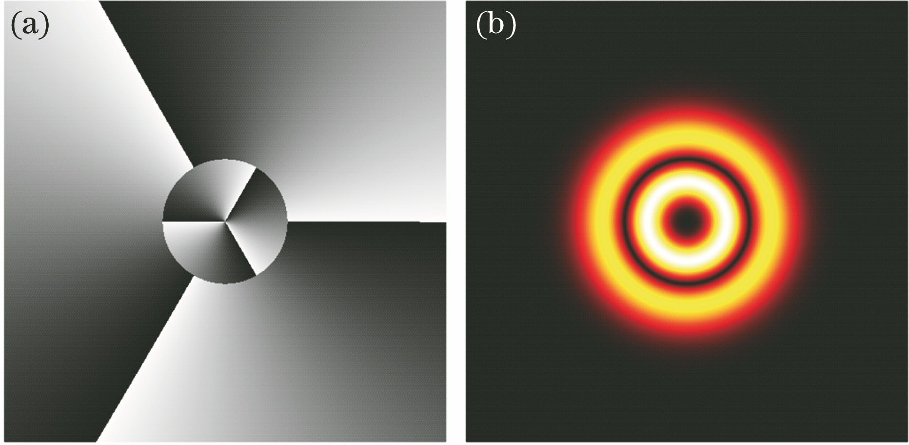
    Fig. 1. Phase and intensity of Laguerre-Gaussian beams with p=1 and m=3. (a) Phase; (b) intensity
    Light intensity produced by the coherent superposition of U0,10 and U0,3. (a) Theoretical result; (b) experimental result
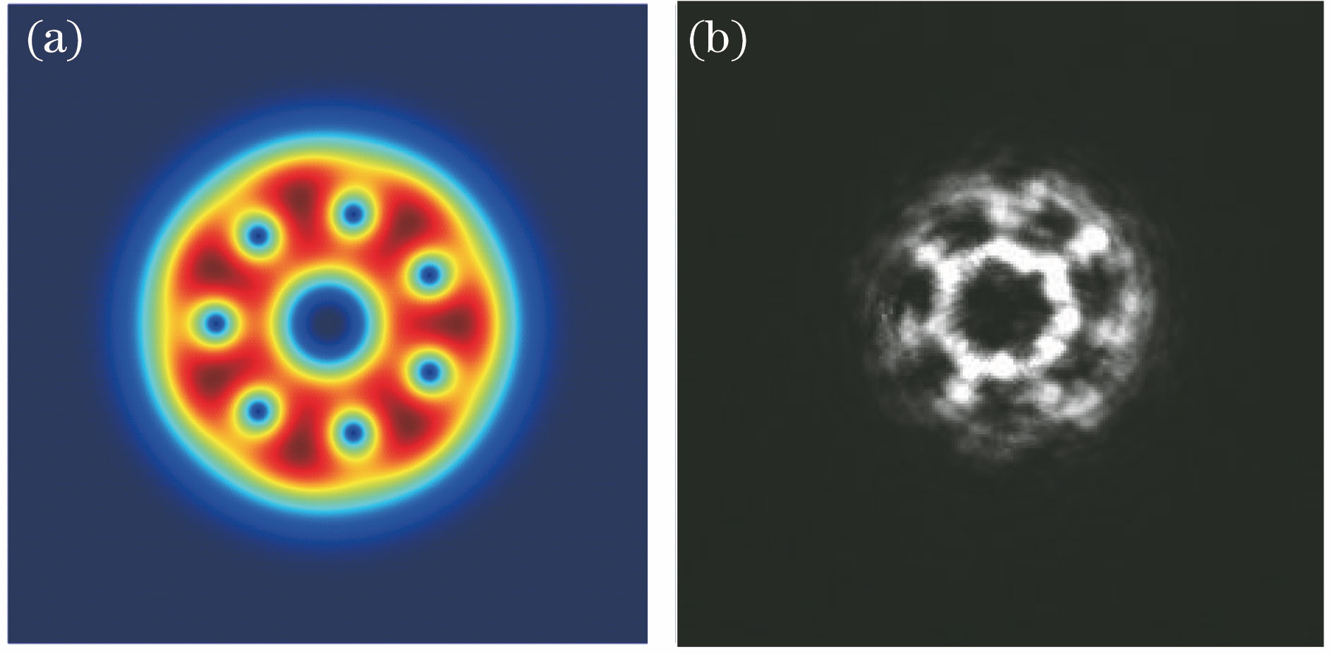
    Fig. 2. Light intensity produced by the coherent superposition of U0,10 and U0,3. (a) Theoretical result; (b) experimental result
    Structure diagram of multiband multiband vortex optical communication system
    Fig. 3. Structure diagram of multiband multiband vortex optical communication system
    Dual-channel multiband modulation signal. (a) First signal; (b) second signal
    Fig. 4. Dual-channel multiband modulation signal. (a) First signal; (b) second signal
    Encoding method
    Fig. 5. Encoding method
    16 kinds of superimposed light intensity correlations. (a) Beam groups {U0,4,U0,6,U0,8,U0,10} and {U0,2,U0,3,U1,2,U1,3}; (b) beam groups {U0,4,U0,6,U0,8,U0,10} and {U0,-2,U0,-3,U1,2,U1,3}
    Fig. 6. 16 kinds of superimposed light intensity correlations. (a) Beam groups {U0,4,U0,6,U0,8,U0,10} and {U0,2,U0,3,U1,2,U1,3}; (b) beam groups {U0,4,U0,6,U0,8,U0,10} and {U0,-2,U0,-3,U1,2,U1,3}
    Phase distribution diagrams corresponding to 16 symbols. The left side represents the phase diagrams, the middle represents the theoretical simulation diagrams at z=0 m, and the right side is the light intensity diagrams recorded by the CCD camera at z=1 m
    Fig. 7. Phase distribution diagrams corresponding to 16 symbols. The left side represents the phase diagrams, the middle represents the theoretical simulation diagrams at z=0 m, and the right side is the light intensity diagrams recorded by the CCD camera at z=1 m
    Atmospheric turbulence phase simulation diagram at Cn2=1×10-14 m-2/3. (a) 3D simulation; (b) phase screen
    Fig. 8. Atmospheric turbulence phase simulation diagram at Cn2=1×10-14 m-2/3. (a) 3D simulation; (b) phase screen
    Light intensity diagrams under different atmospheric turbulence conditions. (a) Cn2=1×10-17 m-2/3; (b) Cn2=1×10-14 m-2/3
    Fig. 9. Light intensity diagrams under different atmospheric turbulence conditions. (a) Cn2=1×10-17 m-2/3; (b) Cn2=1×10-14 m-2/3
    Structure diagram of VGG16 model
    Fig. 10. Structure diagram of VGG16 model
    Training data set
    Fig. 11. Training data set
    Test accuracy and test loss during training process
    Fig. 12. Test accuracy and test loss during training process
    Symbol encodingSelected beamLight intensity shape description
    0000U0,2+U0,42 petals
    0001U0,2+U0,64 petals
    0010U0,2+U0,86 petals
    0011U0,2+U0,108 petals
    0100U0,3+U0,41 petal
    0101U0,3+U0,63 petals
    0110U0,3+U0,85 petals
    0111U0,3+U0,107 petals
    1000U1,2+U0,4Two layers, 2 petals on the outer layer
    1001U1,2+U0,6Two layers, 4 petals on the outer layer
    1010U1,2+U0,8Two layers, 6 petals on the outer layer
    1011U1,2+U0,10Two layers, 8 petals on the outer layer
    1100U1,3+U0,4Two layers, 1 petal on the outer layer
    1101U1,3+U0,6Two layers, 3 petals on the outer layer
    1110U1,3+U0,8Two layers, 5 petals on the outer layer
    1111U1,3+U0,10Two layers, 7 petals on the outer layer
    编码理论和方法如下。①双通道,每一个信道可选择的光束集为四种LG光束,比如选择{U0,2,U0,3,U1,2,U1,3}和 {U0,4,U0,6,U0,8,U0,10}两组光束,记录下不同的花瓣数和光强信息。②为了提高识别的效果,使用阶数为1和0的两种LG光束,叠加后产生的光强将会被分成两层和单层两个种类。③涡旋光束的拓扑荷值选择4,6,8,10,叠加后将产生不同的花瓣,为了提高识别效果,尽可能大地增加叠加光强的差异性,因此使用的1阶和0阶涡旋光束的拓扑荷值有两种2和3,那么第二组光束中拓扑荷值的下标至少应该相差2。④如果不满足两组光束之间的拓扑荷值和阶数之间的关系,那么导致的结果仅仅是只增加了光强图案的大小,并不能改变形状。
    Table 1. Coding results of 16 kinds of symbols in beam sets {U0,4,U0,6,U0,8,U0,10} and {U0,2,U0,3,
    Jiuhang Nan, Yiping Han. Dual-Channel Multiband Vortex Optical Communication[J]. Acta Optica Sinica, 2021, 41(12): 1206001
    Download Citation