
Bin Ma, Jiaqi Han, Ke Wang, Qiushi Huang, Hongfei Jiao, Shuang Guan. Distribution characteristics of metal film eruption induced by nanosecond pulse laser[J]. Infrared and Laser Engineering, 2021, 50(11): 20210036
- Infrared and Laser Engineering
- Vol. 50, Issue 11, 20210036 (2021)
Abstract
0 Introduction
The ejected particles or vaporized metal atoms caused by laser-induced optical elements damage are actively injected into the central high-temperature plasma region of the Tokamak device. From this step, we can infer the plasma disturbance and intensity distribution and analyze the correlation between the injected particles and plasma[
During eruption, a small portion of the metal film peels off and is jolted by a reverse force to start flying outwards, which is similar to the ejection of particles[
Energy Dispersive Spectroscopy (EDS) is used to evaluate the information on deposited atoms by detecting the relevant elements and obtaining the relative atomic ratio and quality ratio of different elements[
In this paper, we aim to develop an estimated method for calculating the number of particles ejected from a metal film layer irradiated by a single pulsed laser. By preparing a series of standard samples and calibrating the EDS detection depth, information on the escape intensity of specific signals of metal elements at different depths is obtained. Moreover, the amount of metal elements deposited on the external receiving plate is estimated. By using pump-probe imaging technology, the transient eruption characteristics of metal films are captured, the differences between the vacuum and atmospheric environments are evaluated. On the basis of the deposited atomic ratio of different experimental conditions, the factors influencing metal eruption are analyzed.
1 Experimental setup
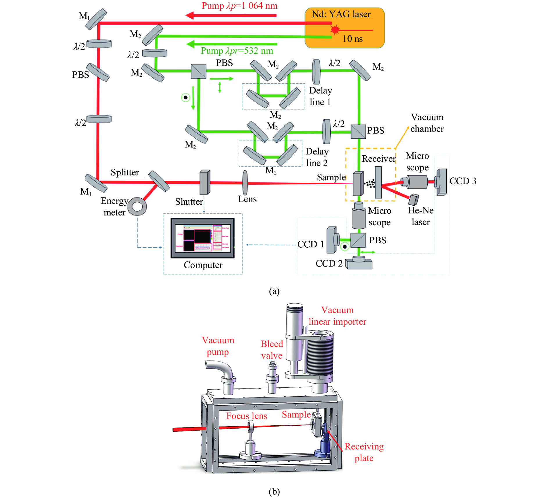
As shown in Fig.1(a), the Laser-Induced Damage Threshold (LIDT) measurement system that includes pump-probe imaging technology is used. The 1064 nm wavelength laser with 10 ns pulse width is used as the pump laser, whereas the 532 nm wavelength laser with 8.5 ns pulse width is used as the probe laser. The transient process of metal film ejection at different times is captured by adjusting the length of the relative path of the two beams. Using a lens with a focal length of 300 mm, the spot diameter is determined to be approximately 0.1 mm. The particle receiving plate is placed behind 25 mm of the sample; information on the submicron-sized particles is monitored by an online microscope. The atomic-state metal elements formed by thermal evaporation are deposited on the receiving plate, and the distribution of the elements is measured by EDS. Figure 1(b) shows the small vacuum devices employed to obtain a low vacuum degree of about 100 Pa by using a mechanical pump. Thus, the differences in the characteristics of metal film eruptions under vacuum and atmospheric environments can be compared and analyzed.
![]()
Figure 1.Schematic of experimental equipment. (a) LIDT test system with pump-probe technology; (b) A small vacuum system
2 Evaporation model of metal film
2.1 Distribution of Al atoms
To calculation of particle number, the proportion of metal elements on the receiving plate is measured by EDS. After ejection, the ratio of the metal elements reaching the receiving plate to the total number of metal elements ejected is calculated. The calculation is divided into two parts: (1) the number of particles of metal elements in the damaged area is determined, and (2) the number of particles of metal elements on the receiving plate is computed.
The number of particles of metal films ejected is N1, which is expressed as:
where
The distribution area of the particles on the receiving plate is a circle. Starting from the center of the circle, along a certain direction of the radius, r is a fixed distance for the EDS test and the test areas S are all the same until the metal elements no longer appear. The result of the EDS test is the proportion of metal elements in several different test areas, which is
The number of metal particles received on the receiving plate is N2, which is expressed as:
where
where
Finally, the percentage of particles of metal elements received by the receiving plate
Then, the experimental results are calibrated by a series of standard samples. Using the aforementioned method to calculate the density of the number of particles of metal elements in the EDS test area, the number of particles in area S and depth h is approximately considered as the total number of test particles in the volume. However, the number of particles that EDS can detect plummets with the penetration depth. Therefore, the result needs to be corrected and calibrated. The steps for producing the standard sample are as follows:
(1) An Al film layer is coated with a thickness of d0 (1 µm) on a fused silica substrate, marked as Class I sample;
(2) SiO2 film layers of different thicknesses are coated onto Class I sample; the thicknesses of the SiO2 film layers are integral multiples of 0.25 µm, marked as Class II samples;
(3) The Al ratio of Class I and Class II samples are measured by EDS, and the Al ratio of Class II samples are modified by using the measurement results of Class I sample;
(4) The thickness of the SiO2 film layer and the modified Al ratio curve are plotted. When the Al ratio is 0, the thickness of the SiO2 film layer is the penetration depth of EDS.
As shown in Fig.2, the EDS penetration depth is approximately 1.65 μm, and the total number of particles detected in Equation (3),
![]()
Figure 2.EDS measurements of 1 µm Al layer embedded in different depths of SiO2 film. The horizontal coordinate is the thickness of the SiO2 film layer, and the ordinate is the proportion of the quality of Al elements obtained by EDS. The measuring area is 50 μm×100 μm, the scanning time is 25 s, and the electron beam energy is 10 keV
where
Equation (3) becomes:
where
Under very high laser fluence, the metal layer and substrate of the Class I sample are damaged simultaneously, and most of the ejected particles are microns in size. The main component is SiO2, which is mainly from the substrate itself, and the metal elements adhere to the SiO2 particles. By contrast, under proper laser fluence, only the metal layer is damaged, and thermal evaporation ejects additional particles in atomic and ionic states. After a period of ejection and flight, the particles are deposited on the surface of the receiving plate. Through EDS measurements, the relative mass ratio of the metal elements can be obtained. The experimental results show that most of the metal elements are distributed within 2 mm on the receiving plate center which is placed 40 mm behind the sample, and the size of the film-peeling area is about 100–200 μm by 0.1 mm laser spot diameter.
2.2 Impact of environment and laser fluence
Differences in environments and laser fluences. Using Equations (1), (2), (4) and (6), the total number of atoms ejected by the Al film layer, the total number of atoms deposited on the receiving plate, and the deposited proportion can be determined. The distribution characteristics of Al elements on the receiving plate under different laser fluences in the atmospheric and vacuum environments are compared. As shown in Fig.3 and Tab.1, the thickness of Al film is 1 μm, which is coated by electron beam evaporation. The total number of ejected particles, the number of deposited particles, and the deposited proportion are roughly calculated. Figure 4 gives the damage morphology of Al film. Because of the stable film structure and the small internal stress, the damage morphology shows to be symmetrical.
![]()
Figure 3.Distribution characteristics of Al particles in atmospheric and vacuum environments under different laser fluences
| Environment | Laser fluence/J·cm−2 | Total ejected particles | Total received particles | Percentage of reception |
| Atmosphere | 33 | 1.2481×10¹⁶ | 7.2583×10¹⁵ | 58.16% |
| 42 | 1.3814×10¹⁶ | 7.2847×10¹⁵ | 52.73% | |
| 50 | 1.9798×10¹⁶ | 1.0892×10¹⁶ | 55.01% | |
| Vacuum | 33 | 1.2011×10¹⁶ | 4.8924×10¹⁵ | 40.73% |
| 42 | 1.4448×10¹⁶ | 5.6541×10¹⁵ | 39.13% | |
| 50 | 2.0198×10¹⁶ | 7.3754×10¹⁵ | 36.52% |
Table 1. Number of Al particles received by the receiving plate under different conditions
![]()
Figure 4.Damage morphology of Al film deposited by electron beam evaporation
Under the same laser fluences, the size of the damage of Al films in the atmospheric environment is close to that of the vacuum environment. In the atmospheric environment, about 50%-60% of the metal particles are usually received by the receiving plate. In the vacuum environment, this proportion is slightly lower. Because the oxygen-assisted combustion and reinforcement of plasma mass will not occur in the process of metal film damage, in which the plasma eruption will exert a secondary heating and kinetic energy transfer impact on metal atoms. Figure 5 shows the transient images of Al film in vacuum and atmospheric environment. The light of the detection area in the transient images is shielded, and a black region is formed. The transient eruption profile of the metal is related to the melting point, heat transfer coefficient, local temperature, flammability, and level of thermal evaporation. By comparison, it is easier to form strong plasma region in atmospheric environment. Moreover, in the atmospheric environment, the blocking effect of atmospheric molecules on the ejected atoms during flight is not significant.
![]()
Figure 5.Transient ejection characteristics of Al film at 90 ns in different environments captured by pump-probe image technology. (a) Atmospheric environment; (b) Vacuum environment
2.3 Difference of different metal films
Compared with Al film, W film has a higher melting point (Al has a melting point of 660 ℃ and W has a melting point of 3410 ℃). The eruption process caused by thermal damage is affected by the high melting point and heat transfer of W film, which is significantly different from Al. In particular, the thermal stress required to cause damage of the same size and thermal evaporation effect is greater, and the laser energy is stronger.
Figure 6 shows the ejection transient images of 5 µm thick Al and W films in a vacuum environment at 90 ns delay. The ejection morphology is related to the metal characteristics, and the difference is very obvious. These characteristics also determine the distribution and proportion of the ejected atomic metal elements, as shown in Tab.2 and Fig.7. The receiving plate receives W significantly less than Al.
![]()
Figure 6.Transient image of (a) Al and (b) W film ejection in 90 ns under vacuum environment
| Environment | Fluence/J·cm−2 | Element | Total ejected particles | Total received particles | Percentage of reception |
| Atmosphere | 33 | Al | 1.39428×10¹⁶ | 9.04330008×10¹⁵ | 64.86% |
| W | 1.09506×10¹⁶ | 2.28100998×10¹⁵ | 20.83% | ||
| Vacuum | 33 | Al | 1.34463×10¹⁶ | 7.80557715×10¹⁵ | 58.05% |
| W | 8.71092×10¹⁵ | 1.965183552×10¹⁵ | 22.56% |
Table 2. Number of Al and W particles received by the receiving plate under different conditions
![]()
Figure 7.Distribution characteristics of Al and W element on the receiving plate in atmospheric and vacuum environments
3 Conclusion
In addition, with the increase in laser fluence, the number of atoms received and the ejection angle increase, mainly concentrated in the range of 16°–20°, but the overall atomic reception ratio has not changed substantially or even slightly decreased due to loss effect.
Laser-induced thermal-mechanical damage causes the metal film layer to peel off. Only the metal layer is damaged, the metal is heated until it evaporates, forming an eruption of steam mass. It can be inferred that if the film structure is loose, uneven, too thick, or high stress inside, then residual debris is ejected. This phenomenon can substantially reduce the number of particles deposited on the receiving plate. Also, if the melting point is high and the metal is flammable, then the entire film layer evaporates incompletely both in the atmospheric and vacuum environments. A large number of molten particles will form uniform distribution, even in the molten state or as droplet-type debris, thereby reducing the number of particles deposited on the receiving plate.
In sum, by preparing a standard sample for EDS tests, the penetration depth of EDS is calibrated and the specific X-ray escape ratio at different depths is obtained. Then, the distribution of metal elements on the sample surface is approximately analyzed by EDS measurements. This method is necessary to estimate the number of atoms deposited after laser-induced thermal evaporation of a metal layer. Moreover, the number of deposited atoms of Al in the vacuum and atmospheric environments is calculated, and a detailed analysis and explanation are provided.
References
[1] R Guirlet, D Villegas, T Parisota, et al. Anomalous transport of light and heavy impurities in Tore Supra sawtooth-free ohmic plasmas. Nuclear Fusion, 49, 055007(2009).
[2] K Zhang, Z Y Cui, P Sun, et al. Investigation of impurity transport using laser blow-off technique in the HL-2A Ohmic and ECRH plasmas. Chinese Physics B, 25, 065202(2016).
[3] S G Demos, R A Negres, R N Raman, et al. Relaxation dynamics of nanosecond laser superheated material in dielectrics. Optica, 2, 765-772(2015).
[4] A Salleo, S T Taylor, M C Martin, et al. Laser-driven formation of a high-pressure phase in amorphous silica. Nature Materials, 2, 796-800(2003).
[5] S Papernov, A W Schmid. Two mechanisms of crater formation in ultraviolet-pulsed-laser irradiated SiO2 thin films with artificial defects. Journal of Applied Physics, 97, 114906(2005).
[6] S Rui, M Z Xiang, J Chen, et al. Molecular dynamics simulation of shock induced ejection on fused silica surface. Journal of Applied Physics, 115, 27708(2014).
[7] J Y Natoli, L Gallais, H Akhouayri, et al. Laser-induced damage of materials in bulk, thin-film, and liquid forms. Applied Optics, 41, 3156-3166(2002).
[8] A A Manenkov. Fundamental mechanisms of laser-induced damage in optical materials: today’s state of understanding and problems. Optical Engineering, 53, 010901(2014).
[9] Ma B, Zhang Y Y, Ma H P, et al. Highly sensitive compact refractive index sens based on phaseshifted sidewall Bragg gratings in slot waveguide [J]. Applied Optics, 2014, 53(1): 96103.
[10] M L Lu, B Ma, G D Zhan, et al. Effect of etching on the laser-induced damage properties of artificial defects under 1064 nm laser irradiation. Optical Engineering, 53, 122505(2014).
[11] X B Cheng, J L Zhang, T Ding, et al. The effect of an electric field on the thermomechanical damage of nodular defects in dielectric multilayer coatings irradiated by nanosecond laser pulses. Light: Science & Applications, 2, e80(2013).
[12] L Gallais, J Y Natoli, C Amra. Statistical study of single and multiple pulse laser-induced damage in glasses. Optics Express, 10, 1465-1474(2002).
[13] J Bude, P Miller, S Baxamusa, et al. High fluence laser damage precursors and their mitigation in fused silica. Optics Express, 22, 5839-5851(2014).
[14] R N Raman, R A Negres, S G Demos. Kinetics of ejected particles during breakdown in fused silica by nanosecond laser pulses. Applied Physics Letter, 98, 051901(2011).
[15] S G Demos, R A Negres, R N Raman, et al. Material response during nanosecond laser induced breakdown inside of the exit surface of fused silica. Laser & Photonics Reviews, 7, 444-452(2013).
[16] N Zhang, X Zhu, J Yang, et al. Time-resolved shadowgraphs of material ejection in intense femtosecond laser ablation of aluminum. Physical Review Letters, 99, 167602(2007).
[17] Goldstein J I, Newbury D E, Michael J R, et al. Scanning Electron Microscopy XRay Microanalysis [M]. US: Springer, 2018.
[18] J H Park, J Seo, S Park, et al. Efficient CH3NH3PbI3 perovskite solar cells employing nanostructured p-type NiO electrode formed by a pulsed laser deposition. Advanced Materials, 27, 4013-4019(2015).


Set citation alerts for the article
Please enter your email address

© Copyright 2018-2021 | Chinese Laser Press. All Rights Reserved 沪ICP备15018463号-20