
Wei Song, Jing Liang, Haiqiao Zhang, Linyong Shen, Ya’nan Zhang, Yang Zhou. Laser Navigation and Mapping Based on Building Environment Classification[J]. Laser & Optoelectronics Progress, 2021, 58(14): 1404001
- Laser & Optoelectronics Progress
- Vol. 58, Issue 14, 1404001 (2021)
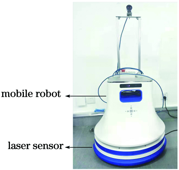
Fig. 1. The mobile robot
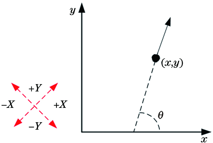
Fig. 2. Pose of a mobile robot in the two-dimensional coordinate system
Fig. 3. Images from laser sensor. (a) Original local image from laser sensor; (b) local image from laser sensor after normalization
Fig. 4. Images after threshold segmentation
Fig. 5. Local maps of different scenes. (a) End of the corridor; (b) straight corridor; (c) corridor corner
Fig. 6. Vertical projection and horizontal projection of local maps in different scenes. (a) End of the corridor; (b) straight corridor; (c) corridor corner
Fig. 7. The robot enters the T-shaped corner in different orientations
Fig. 8. Structure diagram of classifiers
Fig. 9. Straight scene. (a) Straight corridor; (b) straight T-shaped corner
Fig. 10. Interference line segment filtering
Fig. 11. Right turn corner
Fig. 12. End of the corrido
Fig. 13. The experimental environment
Fig. 14. Path planning for straight area
Fig. 15. Path planning for corner area
Fig. 16. Path planning for the end area
Fig. 17. Construction effect of global map. (a) Viewable navigation path; (b) environmental raster map
|
Table 1. Effects of the classifiers

Set citation alerts for the article
Please enter your email address
© Copyright 2018-2021 | Chinese Laser Press. All Rights Reserved 沪ICP备15018463号-20