Abstract
Surface coating has long been an effective means to improve the electrochemical performance of electrode materials for Li-ion batteries. In this study, the traditional micron-sized Li4Ti5O12 anodes are coated with amorphous lithium phosphate by radio frequency (RF) magnetron sputtering. The characterized morphology indicates that the electrodes are covered by a thin amorphous lithium phosphate coating layer, showing a very smooth surface. Both the rate performance and cycle performance of the electrodes are enhanced markedly by the coating layer in the voltage range of 0.01-3.00 V. When the discharge-charge currents are 35 and 1750 mA∙g-1, the capacities are elevated to 265 and 151 mAh∙g-1, respectively, which are higher than those of the uncoated ones (240 and 22 mAh∙g-1). After further discharge-charged for 200 cycles at 88 mA∙g-1, the coated electrodes still maintain a high reversible capacity of 238 mAh∙g-1. This result clearly suggests that the thin layer can stabilize the solid electrolyte interface, maintain the integrity of the interparticle electronic passage and form a cross-linked ionic conducting network for Li4Ti5O12 grains on the surface.Spinel Li4Ti5O12, exhibiting excellent reversibility during discharge-charge processes for its intrinsic zero- strain property[1], is expected to be a proper anode material for high power lithium ion battery. Numerous studies have been carried out to improve electronic conductivity by doping and developing various composites. Simultaneously, researches flourish in size tuning and shape controlling. However, the low theoretical capacity of 175 mAh∙g-1 and high Li+ insertion/extraction potential of 1.55 V (vs. Li/Li+) make it less competitive to carbon, silicon and tin based anodes[2].
Recently, Lei and his coworkers[3] proposed that Li4Ti5O12 could be lithiated up to Li8.5Ti5O12 accompanying with a small volume expansion of about 0.4% when discharged to 0.05 V. This attractive finding was arousing new enthusiasm in the field of Li4Ti5O12. Doping with metal ions[4] and preparation of composites[5] were applied to improve the cycle stability as well as the rate performance in the potential range of 0.01-3.00 V. Surface coating is an effective method for material modification as well. Generally, coating methods can be divided into two types: coating the particle surfaces and coating the fabricated electrode directly[6]. For the former case, each particle is expected to be perfectly coated. When Li4Ti5O12 is discharged to 0.01 V, solid electrolyte interface (SEI) film inevitably forms on the surface of the coated particles of active material and acetylene black[7], which impedes the interparticle electronic contact and gives rise to poor rate performance and a possibly resultant poor cycle performance. In contrast, the latter coating method is demonstrated as a newly developed and facile way to enhance the electrochemical performance by maintaining not only the physical features but also the electronic contact of the desired electrode[8].
Amorphous lithium phosphate (Li3PO4), a stable Li+ conductor, is a potential coating material for its strong glass forming character and ease of preparation[9]. Taking into account the combined effect of the hazardous reaction between the particle surface and the electrolyte as well as the SEI formation process, a facile radio frequency (RF) magnetron sputtering method is proposed in this work to coat the as-fabricated electrodes with an amorphous Li3PO4 thin layer. The focus of this work is to enhance the structure stability of the electrodes, stabilize SEI film, maintain the integrity of the electronic passage and form a cross-linked ionic conducting network compensating the possible anisotropic surface lithium insertion.
1 Experimental
1.1 Preparation and characterization of amorphous Li3PO4 coated Li4Ti5O12 electrode
Li4Ti5O12 powder was prepared by a simple solid-state reaction method described in previous work[10]. TiO2 (anatase, AR) and Li2CO3 (industrial grade) were mixed thoroughly and sintered in a tube furnace at 750 ℃ in the air for 12 h. The electrodes were fabricated on Cu foil by a traditional doctor blade method with the weight ratio of active material, carbon black and polyvinylidene fluoride (PVDF) being 8 : 1 : 1. The prepared electrodes were dried at 100 ℃ before use. For RF magnetron sputtering, commercially available Li3PO4 target (99.99%, Jiangxi Hai Te Advanced Material Co., LTD) and the as-prepared electrodes were used as target and substrates, separately. The key parameters were as follows: base pressure, 6×10⁴ Pa; substrate temperature, 100 ℃; working gas, Ar (99.999%, 1 Pa, 30 sccm); substrate rotation speed, 10 r∙min-1; target-to-substrate distance, 4 cm; RF power, 160 W; sputtering time, 10, 20 and 40 min. The as-prepared samples were named as LTOLPO10, LTOLPO20 and LTOLPO40 according to sputtering time. The pristine Li4Ti5O12 electrode was named as LTOLPO00.
1.2 Characterization
The structure and morphology information were collected by XRD diffraction (XRD, χ’pert pro MPD, Cu Kα radiation, 0.03 (°)/s, 2θ=10°-85°), field emission scanning electron microscope (FE-SEM, Hitachi, S3400N) and Raman spectroscope (Renishaw inVia Reflex Raman Microscope, 0.5 mW, 514 nm). As for electrochemical test, two-electrode half cells were assembled with 1 mol∙L-1 LiPF6 solution in ethylene carbonate (EC)-diethyl carbonate (DEC) (1 : 1 in volume) as the electrolyte and Li foil as the counter and reference electrode. The mass loading was approximately 1.3 mg∙cm-2. A LAND series battery testing system (CT2001A/ CT1001C, Wuhan Kingou Electronics Co., Ltd.) was used to evaluate the rate performance and cycling behavior. Electrochemical impedance spectroscopy (EIS) (0.1 Hz-10 MHz, 1.56 V) was conducted on an electrochemical analyzer (Solartron Model 1287/1260A, Solartron Analytical).
2 Results and discussion
2.1 Structure and morphology characterization
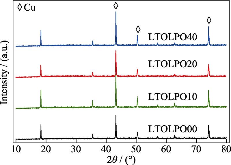
XRD patterns of the prepared electrodes are displayed in Fig. 1. The peaks located at 2θ=18.3°, 35.6°, 43.2°, 57.2° and 62.9° can be assigned to Li4Ti5O12. Alternatively, those peaks positioned at 2θ=43.3°, 50.4° and 74.1° belong to the copper substrate. All of the diffraction peaks of amorphous Li3PO4 coated electrodes match well with those of pristine electrodes, which confirms that surface coating treatment has no serious impact on the crystal structure of the active material. No Li3PO4 diffraction peaks are detected, suggesting the deposited lithium phosphate layer is in amorphous state. To further illustrate the amorphous behavior, the FT-IR absorption spectrum of Li3PO4 deposited on copper foil for 60 min is shown in Fig. S1.

Figure 1.XRD patterns of pristine electrode LTOLPO00 and coated electrodes LTOLPO10, LTOLPO20 and LTOLPO40
Figure S1.FT-IR absorption spectra of Li3PO4 sputtered on copper foil for 60 min
SEM images of the amorphous Li3PO4 coated Li4Ti5O12 electrodes are shown in Fig. 2. As for LTOLPO00, Li4Ti5O12 active materials with the particle size of hundreds of nanometers disperse in the matrix of carbon black nanoparticles. With the coating time increasing, the particle corners of the active materials become blunt. As can be seen, the surface morphology of LTOLPO40 is totally changed. Both of the active species and the surrounding carbon black particles are covered by a thin layer, showing very smooth surface, which is another evidence of amorphous state for the coating layer. Moreover, The EDS result of LTOLPO40 in Fig. S2 indicated the existence of Li3PO4 on the modified Li4Ti5O12 electrode. The neighboring particles are wrapped together with the coating layer, leading to enlarged particles and the cross- linked network.
Figure 2.SEM images of pristine electrode LTOLPO00 (a) and coated electrodes LTOLPO10 (b), LTOLPO20 (c), and LTOLPO40 (d)
Figure S2.EDS result of Li4Ti5O12 electrode sputtered for 40 min (LTOLPO40)
2.2 Electrochemical performance
The first two discharge-charge curves of LTOLPO00 and LTOLPO20 at the current of 35 mA∙g-1 are given in Fig. 3(a, c), separately. Checking the discharge profiles, the plateau at about 1.54 V indicates the coexist of spinel Li8a[Li1/3Ti5/3]16d[O4]32e phase and rock-salt [Li2]16c[Li1/3Ti5/3]16d[O4]32e phase[11]. It should be noticed that, compared with pristine Li4Ti5O12 electrode, the platform of the amorphous phosphate coated electrode is longer. The initial discharge capacity of LTOLPO20 at 1 V is 191 mAh∙g-1, which is a little higher than the theoretical capacity and that of pristine Li4Ti5O12 electrode (171 mAh∙g-1). Similar results were observed in amorphous phosphate coated LiFePO4[12] and Ni-rich LiNi0.6Co0.2Mn0.2O2[13]. For Li4Ti5O12, the electrochemical performance for single crystal epitaxial film of Li4Ti5O12 (111) and Li4Ti5O12 (110) reported by Kanno and his group[14] indicate that Li+ insertion/ extraction mechanism alters with the lattice plane. The capacity of single crystal epitaxial film of Li4Ti5O12 (111) is much higher than that of Li4Ti5O12 (110), resulting in the prolonged plateau as well. The extended platform and the enlarged capacity could be contributed to the maintenance of the integrity of the surface structure most likely detected by HRTEM, especially for Li4Ti5O12 (111), to which the strongest peak in XRD patterns is ascribed[15]. A little plateau can be distinguished in the first discharge profiles at around 0.7 V and disappears in the second discharge profiles, which is mainly contributed to the initial formation of the SEI film on the acetylene black particles[16]. The capacity under 0.6 V is then attributed to further lithiations of rock-salt [Li2]16c[Li1/3Ti5/3]16d[O4]32e phase to quasi-rock-salt phase [Li2/3]8a[Li2]16c[Li1/3Ti5/3]16d[O4]32e, in which 8a sites are also occupied. The discharge capacity discrepancy of the first cycle might be aroused by the different amount of SEI film, which partially indicates the role of amorphous phosphate coating layer as artificial SEI film. The voltage curves at the current density of 175 mA∙g-1 are also shown in Fig. 3(d). An evident extension is observed for the plateau at around 0.57 V under high current density for LTOLPO20, which gives another proof for the key role of amorphous Li3PO4 in protecting Li4Ti5O12 (111) plain and ensuring an easy Li+ insertion/extraction at low potential.
Figure 3.(a, c) First two discharge-charge curves at 35 mA∙g-1, 22nd discharge-charge curve at 175 mA∙g-1 and (b, d) the corresponding differential capacity plots of (a, b) pristine electrode LTOLPO00 and (c, d) coated electrode LTOLPO20
Fig. 3(b, d) exhibit the plots of differential capacities versus the voltages. The reduction peaks located at 1.53 and 1.54 V, respectively, in the first cycle for LTOLPO20 and LTOLPO00, which shift to 1.52 V in the second cycle. As for the oxidation peaks, an unchanged voltage (1.60 V) is detected for LTOLPO20. On the contrary, a small shift from 1.61 to 1.62 V can be distinguished for LTOLPO00. It can be concluded that the polarization of LTOLPO00 tends to intensify even in the first two cycles, which is another sign of the preliminary formation of passivated surface layer[17] as well as consumed larger amount of lithium ions. This result agrees with the instability of the SEI films formed on the particle surface of Li4Ti5O12 depicted in the literature[18]. The polarization further enhanced with the increase of the current density. The sharp redox peaks of LTOLPO20 at 175 mA∙g-1 indicate structure stability for amorphous Li3PO4 coated electrodes. An evident reduction peak located at 0.57 V indicates that the amorphous Li3PO4 coating layer facilitates the phase transformation from rock-salt [Li2]16c[Li1/3Ti5/3]16d[O4]32e phase to quasi-rock-salt Li8a[Li2]16c[Li1/3Ti5/3]16d[O4]32e phase. In contrast, the oxidation peak of LTOLPO00 at 175 mA∙g-1 is broadened due to the nanoscale distributed solid solution of Li4Ti5O12 and Li7Ti5O12[19].
The rate performances of the pristine and coated electrodes exhibit in Fig. 4(a). All of the coated electrodes behave better than the pristine electrode. LTOLPO20 is the best among them. The discharge capacities for LTOLPO20 are 265, 223, 207, 196, 179 and 151 mAh∙g-1, respectively, when discharge-charged at the current density of 35, 88, 175, 350, 875 and 1750 mA∙g-1. When the discharge-charge current density is set back to 35 mA∙g-1, reversible capacity retains 238 mAh∙g-1, comparable to the 10th discharge capacity at the same current rate. The improved rate performance is attributed to the coverage of the amorphous layer which can prevent the formation of SEI film on the interface of lithium phosphate and the particles of active material/acetylene black. The SEM images shown in Fig. S3 demonstrates that the primary electrode is wrapped with a thick coating material (SEI film), while the surface of the modified electrode maintains clear after galvanostatic discharge- charge tests (100 times). A resultant smooth path is thus reserved for electronic transfer[20]. Another non-ignorable reason is that the inter-cross conducting network formed on the active material particles can alleviate the impact of anisotropy in Li+ insertion/extraction process in Li4Ti5O12[18]. The protection of the particle surface from phase transformation also possibly contributes to elevated rate performance, which favors a safe exposure of (111) plane to electrolyte and ensure the fast Li+ insertion/ extraction under the potential of 1 V. Thereafter, the current density is set to 88 mA∙g-1 to test the long cycle performance (Fig. 4(b)). The capacity of all coated electrodes increased slowly with the cycles, and then achieved a stable value. The stable capacity of LTOLPO20 reaches 238 mAh∙g-1, a little higher than that obtains at the 70th cycle when the discharge-charge current density is 35 mA∙g-1 shown in Fig. 4(a). The trend is the same for Li4Ti5O12 electrodes sputtered for 60 min (Fig. S4). The capacity experiences a sustained increase when the cell is discharge-charged at a current density of 88 mA∙g-1 until it reaches the initial reversible capacity (discharge-charged at 35 mA∙g-1) in the first 500 cycles. The slow but sustained increase of capacity gives a hint of the improvement of conductivity for the amorphous Li3PO4 coating layer after possible accommodation of dissolved titanium, which has been systematically reported[21]. On the contrary, a few stages of sharp capacity decline detecting for LTOLPO00 indicate the active material is partially peeled from the current collector or other particles, resulting in electrode degradation. It should be remarked that the capacities decrease slowly within initial few cycles, then become stable prior to 10 cycles for all of the samples, which is attributed to the gradual formation of SEI film[22].
Figure 4.(a) Rate performance and (b) long cycle performance of LTOLPO00-LTOLPO40
Figure S3.SEM images of (a)primary electrode and (b)Li3PO4 modified electrode (LTOLPO40) after being cycled for 100 times
Figure S4.Cycle performance and galvanostatic discharge-charge test profiles of LTOLPO60
The comparison of XRD diffraction and Raman spectra between the as-prepared electrodes and the electrodes after 100 electrochemical cycles are collected in Fig. 5. No obvious peak shift and impurity peaks are detected in XRD patterns (Fig. 5(a)) for both pristine and coated electrodes, demonstrating the intrinsic stability of the general structure of Li4Ti5O12, which agrees with the literature[23]. Checking the Raman spectra shown in Fig. 5(b), the peaks of the pristine and coated electrodes match very well before and after electrochemical cycling. The inserted spectra illustrates the unchanged peak position at 233 cm-1. The result is in good agreement with the XRD data. The slightly intensified fluorescence background of LTOLPO20 is supposed to arise from the amorphous Li3PO4 layer. Compared with the as-prepared electrodes, the fluorescence background increases after 100 cycles, demonstrating the possible amorphous material introduced in discharge-charge process. It is noticeable that the fluorescence background of the bared electrode cycled for 100 times becomes much stronger, partially indicating that a mass of amorphous material formed in electrochemical cycles. The SEI film is supposed to be the main ingredient of amorphous material, which leads to the large polarization and the inevitable capacity degradation of the pristine electrode. On the contrary, the milder SEI film of LTOLPO20 guarantees excellent rate performance and cycle stability.
Figure 5.XRD patterns and (b) Raman spectra of LTOLPO00 and LTOLPO20 before and after discharge-charge tests with inset in (b) showing magnification of Raman shift at 233 cm-1
To further understand the role of the amorphous Li3PO4 coating layer in the electrochemical performance, the AC impedance spectra of the pristine LTO and the coated electrodes tested after electrochemically cycling for 10 and 100 times are shown in Fig. 6. The inset equivalent circuits are employed to fit the EIS plots[24]. Rs is the combined resistance of the electrolyte, separator and ohmic contact. For pristine electrode, the EIS plots of the selected cycles are composed of two overlapped semicircles from high to medium frequency. The intercepts of the first semicircle (Rf1) and CPE1 are related to the resistance and capacity of the SEI film that unavoidably formed when discharged to a low potential of 0.01 V. The intercept of the second semicircle (Rct) and CPE3 reflects the charge transfer resistance on the surface of the active material and the corresponding double layer capacitance. Judging from the fitted data listed in Table 1, both Rf1 and Rct of LTOLPO00 increased dramatically, demonstrating that the SEI film on the particle surface of active material and acetylene black made huge impact on the electrochemical activity. The phenomenon is in accordance with the information collected by Raman spectra. The results of LTOLPO20 are quite different. The most prominent discrepancy is the additional semicircle in EIS plots of LTOLPO20, declaring the existence of the amorphous coating layer. The decrease of Rf2 is attributed to the possible diffusion of Ti4+ into the thin layer and results in the gradually increased capacity. The resistance of the SEI film remains stable when further discharge-charged charging from 10 to 100 times, although a milder increase is detected for Rct. The improvement of Rf1 can be induced by the artificial SEI film (the amorphous Li3PO4 coating layer), which protects the particles of the active material and acetylene black from direct contact with the electrolyte. At the same time, a good conductivity network is formed. Distinguished from the mechanism of Rf1, the promotion of Rct boils partly down to the integrity of the particle surface of Li4Ti5O12 and alleviation of the anisotropy in Li+ insertion/extraction process.
Figure 6.EIS plots and the fitted data of (a) LTOLPO00 and (b) LTOLPO20 after discharge-charged for 10 and 100 cycles with insets showing the corresponding equivalent circuits
| Sample | Cycle No. | Rs/Ω
| Rf1/Ω
| Rf2/Ω
| Rct/Ω
|
|---|
| LTOLPO00 | 10 | 5 | 15 | - | 86 |
| LTOLPO20 | 10 | 5 | 21 | 180 | 54 |
| LTOLPO00 | 100 | 5 | 364 | - | 1019 |
| LTOLPO20 | 100 | 7 | 25 | 146 | 216 |
Table 1.
Fitted data for EIS plots of LTOLPO00 and LTOLPO20 at given cycles
In general, all of the outstanding electrochemical performances achieved by electrode coating is contributed by the follows: firstly, the coating layer forms a good ionic conducting network and alleviates the possible impact of anisotropy of Li+ diffusion, which reduces polarization and results in better rate performance; secondly, the coating layer protects most particles of Li4Ti5O12 and acetylene black from being separated by SEI film unavoidably formed at a low potential of 0.01 V, which can undoubtedly maintain the integrity of an electronic passage; thirdly, the amorphous Li3PO4 can accommodate numerous transition metal ions accompanied with enhanced electronic conductivity, which is suggested to be the possible reason for the gradually increasing capacity during the long cycle tests.
3 Conclusion
Traditionally fabricated Li4Ti5O12 electrodes were coated with amorphous Li3PO4 by RF magnetron sputtering. The electrodes covered by amorphous thin films show a very smooth surface. At 20 min of deposition, the electrodes show a maximum improvement of the rate capability and cycle stability. The capacity remains a high level of 151 mAh∙g-1 when discharge- charged at 1750 mA∙g-1. A high capacity of 238 mAh∙g-1 is achieved after discharge-charged at 88 mA∙g-1 for more than 200 cycles. The milder Rct increase of the modified electrodes during charge-discharge process demonstrates that the amorphous Li3PO4 coating layer is very effective in maintaining the integrity of the electrode structure, enhancing the stability of the solid electrolyte interface and promoting the conducting network among the particles. The magnetron sputtering is an effective approach for surface coatings of electrodes, and using Li3PO4 as a coating layer can be broadened to other electrode materials.
Supporting materials
Supporting materials related to this article can be found at https://doi.org/10.15541/jim20200576.
Support information:
Performance of Amorphous Lithium Phosphate Coated Lithium Titanate Electrodes in Extended Working Range of 0.01-3.00 V
WANG Ying1, ZHANG Wenlong1, XING Yanfeng1, CAO suqun2, DAI Xinyi3, LI Jingze4
(1. School of Mechanical and Automobile Engineering, Shanghai University of Engineering Science, Shanghai 201620, China; 2. Faculty of Electronic Information Engineering, Huaiyin Institute of Technology, Huaian 223003, China; 3. College of Materials and Metallurgy, Guizhou University, Guiyang 550025, China; 4. School of Microelectronics and Solid-state Electronics, University of Electronic Science and Technology of China, Chengdu 610054, China)
The spectrum reveals the following characteristics. The bands in the range 420-570 cm-1 are related to the bending modes of the (PO4)3- anion[1]. The stretching bands of (PO4)3- range from 800 to 1200 cm-1. The prominent band at 867 cm-1 is attributed to symmetric stretching modes[2]. A broad and intense band centered at about 1470 cm-1 with three attached kinks at 1420, 1460 and 1520 cm-1 commendably agrees with the FT-IR absorption spectrum of the amorphous lithium phosphate reported by ELBATAL, et al[3].
References:
[1]MACCARIO M, CROGUENNEC L, DESBAT B, et al. Raman and FTIR spectroscopy investigations of carbon-coated LixFePO4 materials. Journal of The Electrochemical Society, 2008, 155(12): A879-A886.
[2]TAN G Q, WU F, LI L, et al. Coralline glassy lithium phosphate- coated LiFePO4 cathodes with improved power capability for lithium ion batteries. Journal of Physical Chemistry C, 2013, 117(12): 6013-6021.
[3]ELBATAL H A, ABDELGHANY A M, ELBATAL F H, et al. UV-visible and infrared absorption spectra of gamma irradiated CuO-doped lithium phosphate, lead phosphate and zinc phosphate glasses: a comparative study. Physica B: Condensed Matter, 2011, 406: 3694-3703.
References
[1] K ZAGHIB, M SIMONEAU, M ARMAND et al. Electrochemical study of Li4Ti5O12 as negative electrode for Li-ion polymer rechargeable batteries. Journal of Power Sources, 81-82, 300-305(1999).
[2] H CHOI S, T KWON, A COSKUN et al. Highly elastic binders integrating polyrotaxanes for silicon microparticle anodes in lithium ion batteries. Science, 357, 279-283(2017).
[3] Y ZHONG Z, C OUYANG, Q SHI S et al. Ab initio studies on Li4+xTi5O12 compounds as anode materials for lithium-ion batteries. ChemPhysChem, 9, 2104-2108(2008).
[4] A STENINA I, N SOBOLEV A, S YAROSLAVTSEV et al. Influence of iron doping on structure and electrochemical properties of Li4Ti5O12. Electrochimica Acta, 219, 524-530(2016).
[5] S BHATTI H, H ANJUM D, S ULLAH et al. Electrochemical characteristics and Li+ ion intercalation kinetics of dual-phase Li4Ti5O12/Li2TiO3 composite in the voltage range 0-3 V. The Journal of Physical Chemistry C, 120, 9553-9561(2016).
[6] Y WANG, Y REN, Y DAI X et al. Electrochemical performance of ZnO-coated Li4Ti5O12 composite electrodes for lithium-ion batteries with the voltage ranging from 3 to 0.01 V. Royal Society Open Science, 5, 180762(2018).
[7] S JIANG, B ZHAO, Y CHEN et al. Li4Ti5O12 electrodes operated under hurdle conditions and SiO2 incorporation effect. Journal of Power Sources, 238, 356-365(2013).
[8] S JUNG Y, S CAVANAGH A, A RILEY L et al. Ultrathin direct atomic layer deposition on composite electrodes for highly durable and safe Li-ion batteries. Advanced Materials, 22, 2172-2176(2010).
[9] W LI N, X YIN Y, P YANG C et al. An artificial solid electrolyte interphase layer for stable lithium metal anodes. Advanced Materials, 28, 1853-1858(2016).
[10] Y WANG, J ZHOU A, Y DAI X et al. Solid-state synthesis of submicron-sized Li4Ti5O12/Li2TiO3 composites with rich grain boundaries for lithium ion batteries. Journal of Power Sources, 266, 114-120(2014).
[11] X LU, L ZHAO, Q HE X et al. Lithium storage in Li4Ti5O12 spinel: the full static picture from electron microscopy. Advanced Materials, 24, 3233-3238(2012).
[12] Q TAN G, F WU, L LI et al. Coralline glassy lithium phosphate- coated LiFePO4 cathodes with improved power capability for lithium ion batteries. Journal of Physical Chemistry C, 117, 6013-6021(2013).
[13] W LEE S, S KIM M, H JEONG J et al. Li3PO4 surface coating on Ni-rich LiNi0.6Co0.2Mn0.2O2 by a citric acid assisted Sol-Gel method: improved thermal stability and high-voltage performance. Journal of Power Sources, 360, 206-214(2017).
[14] M HIRAYAMA, K KIM, T TOUJIGAMORI et al. Epitaxial growth and electrochemical properties of Li4Ti5O12 thin-film lithium battery anodes. Dalton Transactions, 40, 2882-2887(2011).
[15] L ZHAO, S HU Y, H LI et al. Porous Li4Ti5O12 coated with N-doped carbon from ionic liquids for Li-ion batteries. Advanced Materials, 23, 1385-1388(2011).
[16] S HALL D, R GAUTHIER, A ELDESOKY et al. New chemical insights into the beneficial role of Al2O3 cathode coatings in lithium-ion cells. ACS Applied Materials & Interfaces, 11, 14095-14100(2019).
[17] H BORGHOLS W J, M WAGEMAKER, U LAFONT et al. Size effects in the Li4+xTi5O12 spinel. Journal of the American Chemical Society, 131, 17786-17792(2009).
[18] S GANAPATHY, N WAGEMAKER M J A. Nanosize storage properties in spinel Li4Ti5O12 explained by anisotropic surface lithium insertion. ACS Nano, 6, 8702-8712(2012).
[19] M WAGEMAKER, R SIMON D, M KELDER E et al. A kinetic two-phase and equilibrium solid solution in spinel Li4+xTi5O12. Advanced Materials, 18, 3169-3173(2010).
[20] S JUNG Y, P LU, S CAVANAGH A et al. Unexpected improved performance of ALD coated LiCoO2/graphite Li-ion batteries. Advanced Energy Materials, 3, 213-219(2013).
[21] A MOGUSMILANKOVIC, A SANTIC, M KARABULUT et al. Study of electrical properties of MoO3-Fe2O3-P2O5 and SrO-Fe2O3-P2O5 glasses by impedance spectroscopy. II. Journal of Non-Crystalline Solids, 330, 128-141(2003).
[22] D AHN, C XIAO X J E. Extended lithium titanate cycling potential window with near zero capacity loss. Electrochemistry Communications, 13, 796-799(2011).
[23] H GE, N LI, Y LI D et al. Study on the theoretical capacity of spinel lithium titanate induced by low-potential intercalation. Journal of Physical Chemistry C, 113, 6324-6326(2009).
[24] D LEVI M, G SALITRA, B MARKOVSKY et al. Solid-state electrochemical kinetics of Li-ion intercalation into Li1-xCoO2: simultaneous application of electroanalytical techniques SSCV, PITT, and EIS. Journal of The Electrochemical Society, 146, 1279-1289(1999).