
Yaqing Li, Liguo Wang, Qian Wang. Intensity and Phase Characteristics of Ring Airy-Gaussian Vortex Beam in Atmospheric Turbulence[J]. Laser & Optoelectronics Progress, 2019, 56(14): 140101
- Laser & Optoelectronics Progress
- Vol. 56, Issue 14, 140101 (2019)
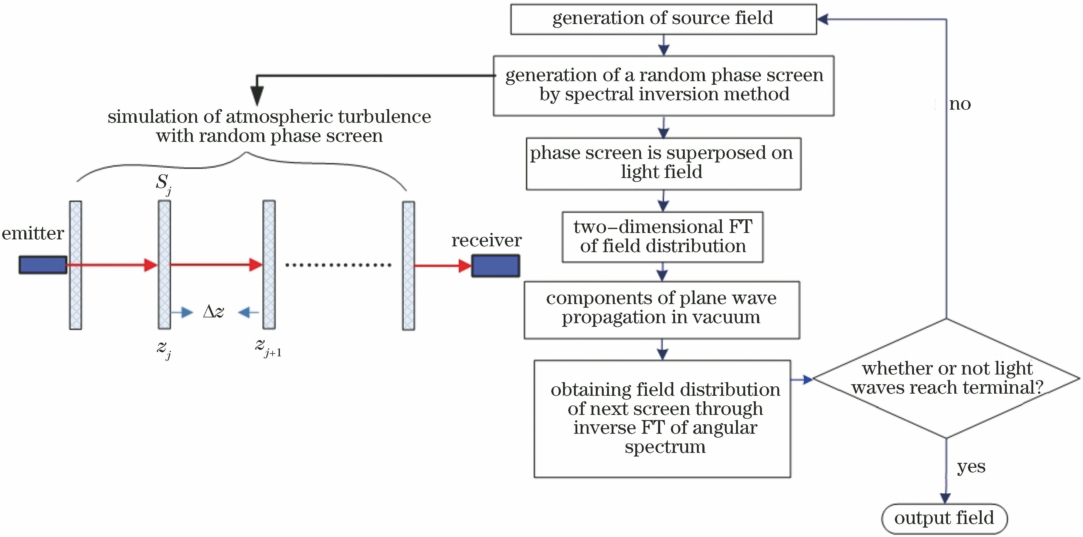
Fig. 1. Flow chart of split-step Fourier method
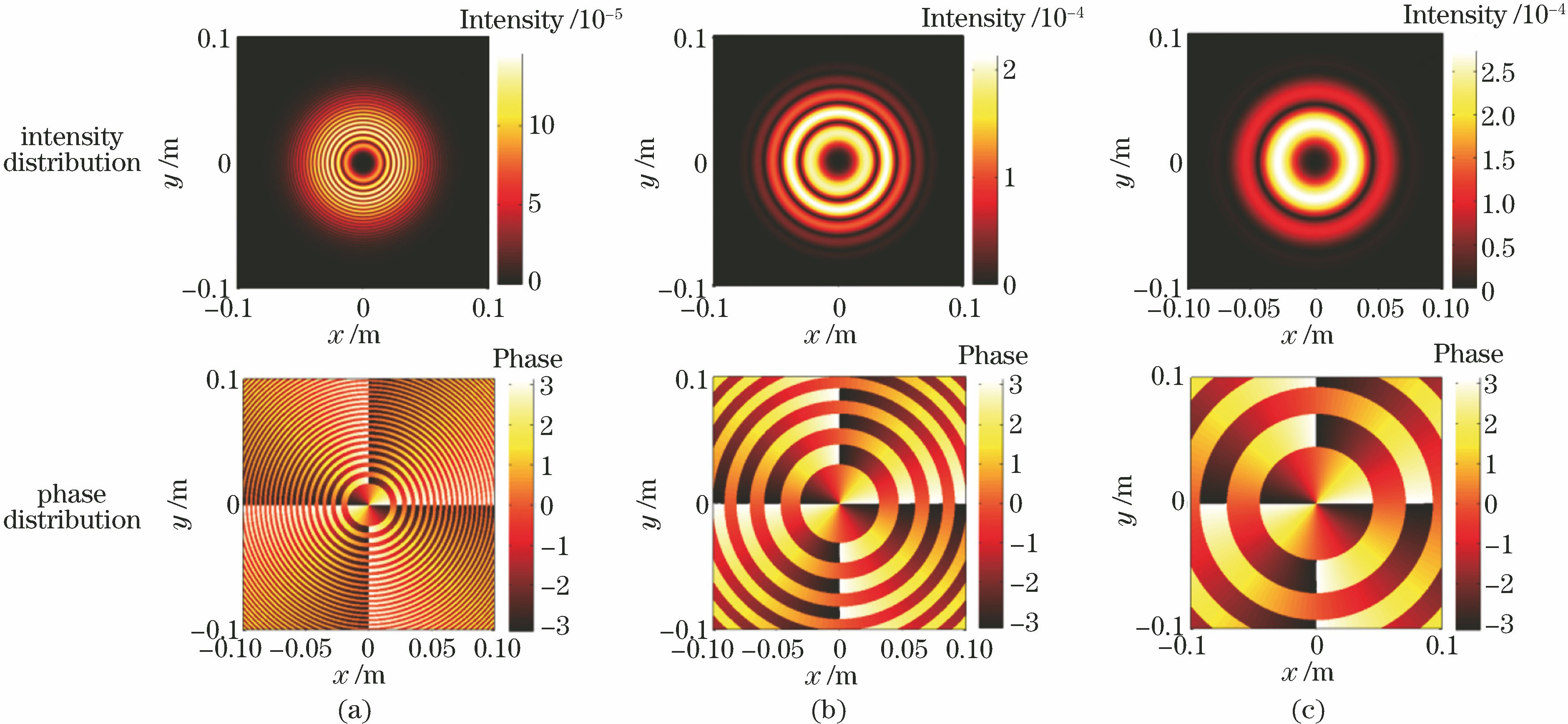
Fig. 2. Intensity distributions at source plane (upper) of RAiGV beam with topological charge of m=2 (a=0.05, r0=0.01 m) in free space and corresponding phase distributions (below). (a) b=0.1; (b) b=0.3; (c) b=0.5
Fig. 3. At source plane, intensities on x axis of RAiGV beam as a function of different parameters. (a) Truncation parameter a; (b) radius of primary Airy ring r0; (c) distribution factor b
Fig. 4. In free space, intensity distributions at source plane (upper) of RAiGV beam with topological charge of m=3 (a=0.05, b=0.3) and corresponding phase distributions (below). (a) r0=0.01; (b) r0=0.03; (c) r0=0.05
Fig. 5. Intensity distributions at different distances L (upper) of RAiGV beam in atmospheric turbulence and corresponding phase distributions (below). (a) L=300 m, b=0.1; (b) L=300 m, b=0.3; (c) L=300 m, b=0.5; (d) L=500 m, b=0.1; (e) L=500 m, b=0.3; (f) L=500 m, b=0.5; (g) L=1000 m, b=0.1; (h) L=1000 m, b=0.3; (i) L=1000 m, b=0.5
Fig. 6. Average intensities of RAiGV beam as a function of propagation distances in atmospheric turbulence under different distribution factors
|
Table 1. Parametersin numerical simulation for RAiGV beam propagation in atmospheric turbulence

Set citation alerts for the article
Please enter your email address
© Copyright 2018-2021 | Chinese Laser Press. All Rights Reserved 沪ICP备15018463号-20