• Photonics Research
  • Vol. 10, Issue 3, 810 (2022)
Wenqiao Shi1, Jianqiang Gu1、5、*, Xingyuan Zhang1, Quan Xu1, Jiaguang Han1, Quanlong Yang2、6、*, Longqing Cong3、7、*, and Weili Zhang4、8、*
Author Affiliations
  • 1Center for Terahertz Waves and College of Precision Instrument and Optoelectronics Engineering, Tianjin University, and Key Laboratory of Optoelectronics Information and Technology, Ministry of Education, Tianjin 300072, China
  • 2Nonlinear Physics Centre, Australian National University, Canberra, ACT 2601, Australia
  • 3Department of Electrical and Electronic Engineering, Southern University of Science and Technology, Shenzhen 518055, China
  • 4School of Electrical and Computer Engineering, Oklahoma State University, Stillwater, Oklahoma 74078, USA
  • 5e-mail: gjq@tju.edu.cn
  • 6e-mail: Quanlong.Yang@anu.edu.au
  • 7e-mail: conglq@sustech.edu.cn
  • 8e-mail: weili.zhang@okstate.edu
  • show less
    DOI: 10.1364/PRJ.440741 Cite this Article Set citation alerts
    Wenqiao Shi, Jianqiang Gu, Xingyuan Zhang, Quan Xu, Jiaguang Han, Quanlong Yang, Longqing Cong, Weili Zhang. Terahertz bound states in the continuum with incident angle robustness induced by a dual period metagrating[J]. Photonics Research, 2022, 10(3): 810 Copy Citation Text show less

    Abstract

    Metasurface-empowered bound state in the continuum (BIC) provides a unique route for fascinating functional devices with infinitely high quality factors. This method is particularly attractive to the terahertz community because it may essentially solve the deficiencies in terahertz filters, sensors, lasers, and nonlinear sources. However, most BIC metasurfaces are limited to specified incident angles that seriously dim their application prospects. Here, we propose that a dual-period dielectric metagrating can support multiple families of BICs that originate from guided mode resonances in the dielectric grating and exhibit infinite quality factors at arbitrarily tilted incidence. This robustness was analyzed based on the Bloch theory and verified at tilted incident angles. We also demonstrate that inducing geometric asymmetry is an efficient way to manipulate the leakage and coupling of these BICs, which can mimic the electromagnetically induced transparency (EIT) effect in our dual-period metagrating. In this demonstration, a slow-light effect with a measured group delay of 117 ps was achieved. The incidence-insensitive BICs proposed here may greatly extend the application scenarios of the BIC effect. The high Q factor and outstanding slow-light effect in the metagrating show exciting prospects in realizing high-performance filters, sensors, and modulators for prompting terahertz applications.

    1. INTRODUCTION

    As a young branch of the electromagnetic spectrum, the terahertz band has broad prospects in many important applications, including fingerprint spectroscopy, security imaging, and wireless communication [1]. Terahertz devices with high quality factors (Q factors), such as highly sensitive sensors [2], narrow linewidth filters [3], and slow-light modulators [4], are indispensable for these applications. The intense photon–matter interaction in high-Q devices is also essential for the renewal of terahertz sources based on lasing and nonlinearity [5], which is expected to fundamentally promote the progress of terahertz technology. Moreover, the research of high-Q devices enables the development of chiral metamaterials [68]. Until now, some high-Q factor terahertz devices based on traditional methods have been reported [2,9,10], but their relatively low values and immature performance still hinder their popularization. Metasurfaces, an artificial meta-atom array enabling strong interactions with the incident light, provide an unprecedented possibility to realize high-Q factors terahertz applications [11,12].

    Bound state in the continuum (BIC), first introduced by von Neumann in quantum mechanics [13], refers to a localized confined mode without radiation located in the continuum spectrum coexisting with waves that have access to the free space, which has been proved to be an efficient way to achieve strong light confinement and find high-Q factor applications [14]. BICs, as a general wave phenomenon, have been identified in electromagnetic waves and initiated many theoretical and experimental investigations. Recently, BICs have been realized in metamaterials or metasurfaces with various perpetually trapped electromagnetic modes leading to infinite Q factors [14]. BIC metasurfaces provide great design freedom to maximize the interaction between light and meta-atoms, thereby bringing great potential in lasing and nonlinear processes, which is important in the generation of terahertz waves. Besides, the ultrahigh Q factor resonance named quasi-BIC (QBIC), resulting from the leakage of BIC, has been demonstrated in metasurfaces as well, which proves to be a promising candidate for terahertz filters, sensors, and slow-light devices that require high-Q factors. So far, kinds of BICs have been proposed based on multiple mechanisms including Friedrich–Wintgen theory [15], resonance trapping [16], surface BIC [17], and symmetry protections [18]. BIC metasurfaces have covered a wide spectral range from optics to the terahertz domain [1928], which provides novel candidates for realizing various terahertz devices with ultrahigh-Q factors. However, most of these metasurfaces were limited to specific incident angles because their BICs can only exist at some specific points in the k-space. Once the incidence is changed (kx,y changed), the bound states start to leak and the Q factor of the metasurface will drop dramatically, which limits the wide spread of the practical applications of BIC-based terahertz devices. Recently, this problem has gradually attracted attention in related studies, but only sporadic solution in anisotropic birefringent materials was reported [29].

    In this work, we demonstrated a route to realize high-Q terahertz metasurfaces with BICs insensitive to the incident angles by exploiting the guided mode resonances (GMRs) in a dual-period dielectric metagrating. We theoretically and experimentally demonstrated that the dual-period silicon metagrating supports two families of BICs, both of which support infinite Q factors at an arbitrary incident angle. Especially, the inverse square dependence between the Q factor and asymmetry is valid over the whole band, which is different from the reported symmetry-protected BICs located at Γ point. By adjusting the symmetry of the structure, the frequency and Q factor of the BIC/QBIC can be manipulated at will. This flexible manipulation capability endows the electromagnetically induced transparency (EIT) analog in the metagrating by the coupling of two QBICs. The measured group delay of the EIT peak achieves a maximum up to 117 ps. The structure proposed here will not only contribute to removing the obstacles in the spread of BIC-based terahertz devices, but also pave the way for the development of high-performance filters, sensors, and modulators at terahertz frequencies.

    2. DEMONSTRATION OF BIC FAMILY

    Figure 1(a) schematically illustrates the design of the proposed dual-period dielectric metagrating. Two different silicon grating ridges [Ridge I and Ridge II as shown in Fig. 1(a)] constitute a supercell with a period of 2Λ=240  μm (Λ is the period of each ridge), a substrate thickness of t=450  μm, and a ridge height of h=50  μm. dx indicates the lateral shift of Ridge I from its original position, and w1 and w2 denote the widths of Ridge I and Ridge II, respectively. Under the conditions of w1+w2=132  μm, we apply dx, w1, and w2 as the main parameters to explore the characteristics of BIC. To minimize the influence of Ohmic loss, the metagratings were made up of high-resistance silicon (ρ>104  Ω·cm) and fabricated by the standard photolithography followed by deep reactive ion etching. The details of fabrication can be found in Appendix A. Figure 1(b) shows the microscopy image of the fabricated dual-period metagrating with high quality.

    Schematic of dual-period dielectric gratings and eigenmode analysis. (a) Schematic illustration of dual-period grating and structural parameters of the grating; (b) microscopy image of the sample; (c) band structure of confined eigenmodes simulated with dual- (green) and mono- (red) period boundary and calculated by the GMR theory (dark blue); (d) electric field distribution of the fourth group of modes at 0.479 and 0.492 THz along the gray axis in the right panel, respectively; the light and dark blue regions indicate the grating layer and substrate, respectively; (e) electric field profile of Ey component based on GMR; upper panel, the frequencies from left to right are 0.370, 0.394, 0.431, and 0.479 THz, respectively; lower panel, 0.371, 0.397, 0.439, and 0.492 THz, respectively.

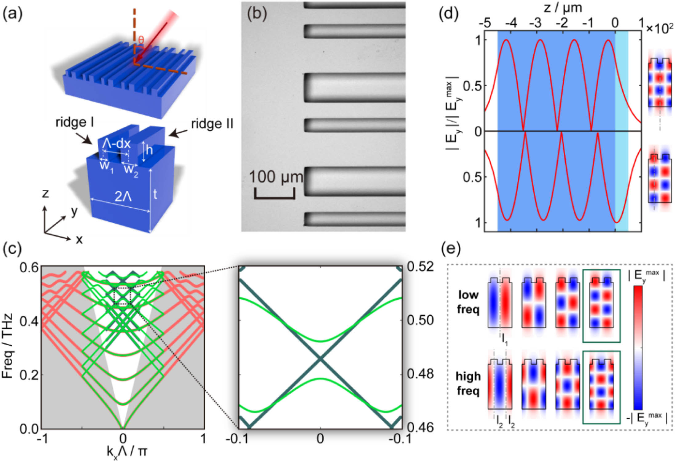
    Figure 1.Schematic of dual-period dielectric gratings and eigenmode analysis. (a) Schematic illustration of dual-period grating and structural parameters of the grating; (b) microscopy image of the sample; (c) band structure of confined eigenmodes simulated with dual- (green) and mono- (red) period boundary and calculated by the GMR theory (dark blue); (d) electric field distribution of the fourth group of modes at 0.479 and 0.492 THz along the gray axis in the right panel, respectively; the light and dark blue regions indicate the grating layer and substrate, respectively; (e) electric field profile of Ey component based on GMR; upper panel, the frequencies from left to right are 0.370, 0.394, 0.431, and 0.479 THz, respectively; lower panel, 0.371, 0.397, 0.439, and 0.492 THz, respectively.

    To interpret the mechanism of the proposed BICs, the intrinsic band structures of TE modes from the dual-period metagrating were investigated by COMSOL Multiphysics. Here, dx=0  μm and w1=w2=66  μm; thus, the grating degenerates to a monoperiod grating with Λ=120  μm. Periodic boundaries were applied on both sides of this supercell. In this scenario, the band structure of the dual-period superlattice (green line) is folded from that of the mono-period unit cell (red line) [30], as shown in Fig. 1(c). Meanwhile, bound states in the discrete region of the monoperiod grating would be folded inside the light cone, which results in bound states in the continuum. In this work, we explored the GMR of the grating as the bound states. The dark blue lines in Fig. 1(c) show the calculated band structure based on GMR theory, which is from the wave-vector matching between the Bloch modes of the grating and the planar waveguide modes [31,32]. The simulated dual-period band structure matches well with the calculated results, except for the bandgaps existing at Γ point in the simulation. This bandgap arises from the fact that there are actually two possible electric field distributions at each theoretically predicted GMR frequency. As illustrated in Fig. 1(d) (taking the GMR modes around 0.492 THz as an example), the electric field distributions of these two modes result in different energies and resonance frequencies, thus forming the bandgap. Figure 1(e) shows the electric field distributions of GMR modes at Γ point locating around 0.370, 0.394, 0.431, and 0.479 THz. The antisymmetric field distributions prevent the modes from radiating to free space, indicating the existence of two types of BICs relating to the antisymmetric axes, l1 and l2, respectively. Another noteworthy observation is that more fields are localized in ridges at 0.479 THz, while fewer fields are confined in ridges at 0.492 THz.

    Since no coupling to free space is allowed for BICs, their experimental demonstration of existence can only be demonstrated by investigating the quasi-BICs where the symmetry of the gratings is broken [21,30,3235]. In this work, the widths of the ridges w1 and w2 were tuned to modulate the low-frequency BICs (w-caused BICs, 0.479 THz) related to l1, while dx of Ridge I was shifted to modulate the high-frequency BICs (dx-caused BICs, 0.492 THz). The corresponding asymmetry factors of these two conditions were defined as αw=(w1w2)/(w1+w2)  and  αdx=dx/(2Λw1w2), respectively. The values of both αdx and αw range from 0 to 1. The simulated transmissions of the symmetry-broken gratings are shown in Fig. 2(a). We also experimentally investigated the evolution of transmission, and the fabricated samples were measured by terahertz time domain spectroscopy (THz-TDS) with a total delay of 600 ps (detailed information of measurement system can be found in Appendix A). The measured results are shown as the solid lines in Fig. 2(b). The transmission T=|Esam/Eref|, where |Esam| and |Eref| are the measured amplitude of the sample and reference. The simulated transmission profile is also plotted in Fig. 2(b) as the dashed line for comparison. In Fig. 2(b), the measured spectra match well with the simulation results except for a slight frequency shift, which may originate from the thickness variation of fabricated samples. In addition, the measured resonances are slightly shallower than simulations and their Q factors are thus lower, which could be attributed to the fabrication error, finite sample size, and limited sampling delay. As shown in Fig. 2(b), the emergence and subsequent broadening of the resonances manifest the evolution of BIC, which starts to leak and degrades to quasi-BIC resonance accompanying the increase of asymmetry factors [14,36]. To quantitatively describe this process, the Q factors of the simulated and measured results were obtained by fitting the spectrum using the Fano formula [37,38], T=|a1+ja2+bωω0+jγ|2,where a1+ja2 represents the background transmission without resonators, b is a real number representing the oscillation amplitude of the resonator, ω0 is the resonance frequency, and γ is the radiation loss. The Q factor was calculated by Q=ω0/2γ and is depicted in Fig. 2(c). For both types of BICs, their Q factors display an inverse proportion to the square of the asymmetry factor, which has also been mentioned in previous symmetry-protected BIC work [18]. In a word, this new resonance and its broadening trend are typical evidences of degradation from BIC to quasi-BIC resonances, which demonstrates that the metagrating holds both types of symmetry-protected BICs simultaneously.

    dx-caused and w-caused BICs in the dual-period grating. (a) and (b) Transmission spectrum with perturbed structural symmetry under normal incidence; (a) and the dashed lines in (b) are the simulated results. The solid lines in (b) are the measured results. (c) Relation between Q factors of the dx-caused quasi-BIC (blue) and w-caused quasi-BIC (red) and α−2. The simulated and measured results are indicated by hollow and solid markers, respectively. (d) Electric field profile in the plane y=0 for different asymmetry at the dip of transmission spectrum; (e) maximum |Ey| of the mode in the plane y=0 under unified incidence with changing asymmetry.

    Figure 2.dx-caused and w-caused BICs in the dual-period grating. (a) and (b) Transmission spectrum with perturbed structural symmetry under normal incidence; (a) and the dashed lines in (b) are the simulated results. The solid lines in (b) are the measured results. (c) Relation between Q factors of the dx-caused quasi-BIC (blue) and w-caused quasi-BIC (red) and α2. The simulated and measured results are indicated by hollow and solid markers, respectively. (d) Electric field profile in the plane y=0 for different asymmetry at the dip of transmission spectrum; (e) maximum |Ey| of the mode in the plane y=0 under unified incidence with changing asymmetry.

    Although w-caused and dx-caused BICs display similar behaviors, two discrepancies should be emphasized here. First, as α increases, the frequency of dx-caused quasi-BIC is almost unchanged, while w-caused quasi-BIC has an obvious blueshift. Second, for the same asymmetry, i.e., when αdx=αw, the dx-caused quasi-BIC has a Q factor fourfold the w-caused one. To understand these discrepancies, the simulated electric field profiles in the plane y=0 at the resonance frequencies are depicted in Fig. 2(d). As the asymmetric factor α increases, it is obvious that more energy of the BICs leaks to the free space. Also, we extracted the maximum of |Ey| at the plane of y=0  μm, which is shown in Fig. 2(e), further illustrating the comparison between the confinement of dx- and w-caused quasi-BIC. In both cases, the field confinement is weakened with increasing asymmetry. However, dx-caused BICs reveal better electric field confinement because more energy of dx-caused BICs exists in the substrate than that of w-caused ones, which results in a small frequency shift and energy leakage.

    More importantly, the BICs supported in the dual-period metagrating possess great robustness over broad incident angles, which has rarely been reported in previous research. Here we explain this advantage by investigating the Q factors of the BICs and quasi-BICs at varied incident angles and with different asymmetry factors, respectively. By using Bloch theory, the Q factor of the metagrating was deduced to be inversely proportional to the square of the asymmetry, Q(kx)=Q0(kx)α2,where Q0(kx) indicates the Q factors when α=1 (see detailed derivation in Appendix B). This equation was testified numerically in w-caused BICs with constant αw=0 and varied αdx ranging from 0 to 0.16. The results can be categorized into two cases. First, when both αdx and αw equal 0, as shown in Figs. 3(a) and 3(b), BICs are protected by the dual-period characteristic. The eigenfrequency of the metagrating presents a redshift as the wave vectors increase, but more importantly, the Q factors are constantly high up to 10131017 without a decaying tendency, in accordance with Eq. (2) when αw=αdx=0. In general, symmetry-protected BIC at Γ point is sensitive to the incident angle, and any declination will induce a dramatic change in the Q factor [39,40]. However, our dual-period metagrating provides a family of BICs [the black circles in Fig. 3(b)] over the whole band, and the Q factors of these BICs obey Eq. (2), thus keeping extremely high for all kx. In the second case, when αdx0 (here varying from 0.005 to 0.16 as examples) while αw=0, the Q factors of these quasi-BICs for each kx are at least 5 orders lower than those in the BIC case. The calculated Q factors of these quasi-BICs precisely obey the inverse square relationship with the asymmetry factor. The distinct Q factors in BIC and quasi-BICs found here indicate that the dual-period-protected BICs in the metagrating are truly incidence-insensitive. The measured results verified this conclusion, as shown in Fig. 3(c). We measured the transmission spectrum of the corresponding samples with different asymmetries αdx (0, 0.370, and 0.555) under a series of incident angles (0°, 2°, 4°, and 6°) while keeping αw=0 as a constant. The cyan regions denote the evolution of quasi-BIC with the increase of the incident angle. It can be seen that in the BIC case (αw=αdx=0), no observable resonance exists for any tilted incidence, while for αdx0, the quasi-BIC resonance changes its frequency and Q factor, as pointed out by Fig. 3(b). The incidence robustness proved here was supported by the BIC family and rarely reported in previously reported symmetry-protected BIC structures [3942], which may provide great advantages in practical applications lacking a strict normal illuminance and lead to a much wider utilizing scenario.

    Investigation of w-caused BIC and quasi-BIC under tilted incidence with dx slide. (a) w-caused BIC band in the first Brillouin zone with αdx=0; (b) Q factors of w-caused BIC band (black circle) in symmetric structure and quasi-BIC band (circles of red, orange, yellow, green, cyan, and blue) with varying αdx (0.005, 0.01, 0.02, 0.04, 0.08, and 0.16); the gray area reveals the discrete region for the band in (a). (c) The measured spectrum with αdx=0, 0.370, and 0.555 under normal and tilted incidence. The cyan regions denote the evolution of quasi-BIC correlated to incident angle.

    Figure 3.Investigation of w-caused BIC and quasi-BIC under tilted incidence with dx slide. (a) w-caused BIC band in the first Brillouin zone with αdx=0; (b) Q factors of w-caused BIC band (black circle) in symmetric structure and quasi-BIC band (circles of red, orange, yellow, green, cyan, and blue) with varying αdx (0.005, 0.01, 0.02, 0.04, 0.08, and 0.16); the gray area reveals the discrete region for the band in (a). (c) The measured spectrum with αdx=0, 0.370, and 0.555 under normal and tilted incidence. The cyan regions denote the evolution of quasi-BIC correlated to incident angle.

    3. EIT ANALOG AND EXTREMELY SLOW LIGHT

    The demonstrated w and dx-caused BICs in the dual-period metagrating have many application prospects because of their incidence-independent characteristic. Especially, the extremely narrow linewidth of quasi-BICs can be employed to couple with other modes, thus obtaining a “W”-shaped transmission spectrum with a slow-light transparent window, i.e., an EIT analog [43]. In 2019, Doskolovich et al. suggested that an EIT analog can be realized using quasi-BIC in a double-layer grating [44]. In the same year, Cong et al. demonstrated a quasi-BIC-induced EIT analog by metallic meta-atoms. However, the intrinsic Ohmic loss will deteriorate the group delay [45]. Thus in 2021, Diego et al. experimentally investigated the quasi-BIC-induced EIT analog in an all-dielectric metasurface at microwave frequencies [43]. In this work, the proposed silicon metagrating has negligible material absorption, due to the high resistivity of silicon in the range of 104  Ω·cm. In addition, our dual-period grating has a larger flexibility of modulation compared with mono-period metasurfaces, which extends the means and ability to regulate the EIT analog.

    To investigate the quasi-BIC-caused EIT analogs, w and dx were jointly tuned. First, as shown in Fig. 4(a), we fixed αdx=0.37 and raised αw from 0 to 0.82. The w- [left branch in Fig. 4(a)] and dx-caused [right branch in Fig. 4(a)] quasi-BICs get closer to each other. Around αw=0.82, their coupling supports an obvious EIT-like transmission around 0.487 THz, in which the w-caused quasi-BIC serves as a superradiant mode due to its weaker field confinement, while the dx-caused quasi-BIC plays the role of a subradiant mode. The width of the transparent window, determining the slow-light effect, can be tuned by altering the radiative loss of the subradiant mode [46,47], which was investigated by changing dx under a constant αw=0.82, as depicted in Fig. 4(b). As αdx decreases from 1 to 0, the transparent window stays at 0.487 THz but becomes narrower, meaning the slow-light effect gets more pronounced. The simulated EIT evolution with the asymmetry factor was well supported by temporal coupled-mode theory (CMT) analysis that considers the transmission of the metagrating as the coupling of the w and dx-caused quasi-BICs (see details in Appendix C) [48], t=(rdtd)[tdrdtd+1+1i(γ1ωω1+γ2ωω2)1],where rd and td are background reflection and transmission, γ1 and γ2 are the loss of two quasi-BICs, and ω1 and ω2 are their resonant frequencies, respectively. Ignoring any nonradiative loss, the coupling between two quasi-BICs will generate a transparent peak with 100% amplitude and the linewidth of the peak becomes narrower as the radiation loss of the quasi-BIC decreases (see deduction in Appendix C). In Fig. 4(d), we presented the simulated, fitted, and measured transmission profiles corresponding to the Cases I to III, as marked in Fig. 4(b), respectively. It can be seen that the fitted profiles precisely conform to the simulated results, not only about the EIT-like transmissions, but also about the evolution of the transparent window’s linewidth when tuning the asymmetry factor. Similarly, the measured results follow the same evolution of the EIT profiles, except for the blueshift and the lower Q factor of the transparent windows due to the imperfections in the samples and the limitations in the measurement.

    Manipulation of two quasi-BICs and EIT-like effect. (a) Transmission evolution with varying αw when αdx=0.37. The dark blue circle points out the EIT-like line shape. (b) Simulated transmission evolution with varying αdx when αw=0.82. (c) Profile of electric field Ey of eigenmodes when αdx=0 and αw=0.82; both are at 0.487 THz. (d) Comparison between simulated, fitted, and measured transmission with varying αdx; simulation results are also marked with dashed lines in (b).

    Figure 4.Manipulation of two quasi-BICs and EIT-like effect. (a) Transmission evolution with varying αw when αdx=0.37. The dark blue circle points out the EIT-like line shape. (b) Simulated transmission evolution with varying αdx when αw=0.82. (c) Profile of electric field Ey of eigenmodes when αdx=0 and αw=0.82; both are at 0.487 THz. (d) Comparison between simulated, fitted, and measured transmission with varying αdx; simulation results are also marked with dashed lines in (b).

    Although the EIT analog caused by two quasi-BICs was elaborated above, there is an interesting and important situation that needs to be discussed carefully—that is, whether an EIT analog formed by a BIC and a quasi-BIC can exist. We still use the example shown in Figs. 4(b) and 4(d) for the following analysis, and the situation corresponds to αw=0.82 and αdx=0. As shown in the Case I in Fig. 4(b), the transparent window disappears. However, Eq. (3) says there should be a fully transparent but infinite narrow EIT peak near 0.487 THz as αdx decreases to 0. The further simulation shown in Fig. 4(c) proves that there are two degenerate eigenmodes at 0.487 THz with totally different electric field profiles. The symmetric one is the w-caused quasi-BIC corresponding to the minimum in Case I at 0.487 THz, while the antisymmetric one is the dx-caused BIC. Intuitively, the coupling coefficient of these two modes should infinitely approach zero because of their distribution characteristics. But considering that a BIC has an infinitely narrow linewidth, whether an EIT analog can be formed by a BIC and a quasi-BIC, as predicted by Eq. (3), is still an open question that should be investigated in our future research.

    What is more, due to the ultrahigh Q factor of quasi-BIC, this EIT analog provides a prospective ability to achieve an outstanding slow-light effect [49]. To investigate the ability of the EIT analog, we fabricated a sample with the same geometric scales shown in Case III of Fig. 4 but with a larger total size (2  cm×7  cm), and we measured this new sample with a total sampling delay of up to 1200 ps. The larger size and longer delay were expected to efficiently enhance the achievable Q factors and group delay of the metagrating in the experiment [50]. Additionally, the simulation was also carried out in a time-domain solver with the same sampling delay of 1200 ps. Although the limited sampling delay will lead to noise in the group delay, the simulation time needs to be in accordance to the measurement in order to analyze the result more precisely. It can be seen in Fig. 5(a) that the simulated spectrum presents a typical EIT line shape with a narrow transparent peak at 0.487 THz. The measured result accords with the simulation quite well, as shown in Fig. 5(d). The group delay is calculated by using the formula, tg=dϕ(ω)dω,where ϕ(ω) is the phase shift of the transmission shown in Figs. 5(b) and 5(e) for simulation and measurement, respectively. A simulated group delay of 314 ps in Fig. 5(c) and a measured one of 117 ps in Fig. 5(f) were achieved at nearly the same frequency, respectively, which is superior to the previously reported value of 25.9 ps based on terahertz metamaterials [51]. It is noteworthy that the group delay at the frequency ω2 can reach up to 1/γ2 (see Appendix D), which means that a small leakage γ2 endows a considerable group delay.

    Simulated and measured slow-light effect. (a) Simulated and (d) measured transmission with αdx=0.37 and αw=0.82; (b) simulated and (e) measured phase shift of transmission; (c) simulated and (f) measured group delay.

    Figure 5.Simulated and measured slow-light effect. (a) Simulated and (d) measured transmission with αdx=0.37 and αw=0.82; (b) simulated and (e) measured phase shift of transmission; (c) simulated and (f) measured group delay.

    4. CONCLUSION

    In summary, we theoretically and experimentally investigated terahertz BICs induced by dual-period metagratings. Two types of BICs distinguished by the field distributions were demonstrated based on electric field profiles. Derived from the Bloch theory, we demonstrated that BIC can exist at tilted incidence and form a BIC family that endows incidence robustness to our metagrating, which was verified in the experiments under a series of incident angles. By tuning asymmetry factors, a quasi-BIC induced EIT analog with a narrow transparent transmission window was realized and systematically investigated. A measured group delay up to 117 ps was achieved by strong slow-light effect. The robustness against incidence demonstrated here extends the application scenarios of BIC-based devices. It also paves the way for the generation of terahertz waves through lasing and nonlinearity for its ultrahigh quality factor.

    APPENDIX A: SAMPLE FABRICATION AND THz-TDS

    To meet the design concept the sample was fabricated on a high-resistance silicon wafer with a thickness of 500 μm and conductivity above 10,000 Ω · cm. The sample was fabricated using the following procedure. First, the grating pattern was transferred onto the silicon wafer by photolithographic exposure and development. Second, the grating structure was formed by deep reactive ion etching on the wafer; the photoresist pattern serves as the protecting layer. The size of the fabricated grating sample has a total area of 2  cm×7  cm for Fig. 2 and the case αdx=0 in Fig. 3(c). The area for other samples is 2  cm×7  cm.

    The transmission spectra of the sample were measured using a THz-TDS system. The distance between the transmitting antenna and the sample was around 25 cm, and the aperture of the sample holder was around 1.4 cm, leading to an incident angle of around 1.6°, which can basically be regarded as a collimated beam. The holder was placed on a rotator with the accuracy of 1/800° to sweep the incident angle of the terahertz wave. A lens was placed in front of the receiver to concentrate the transmitted light and improve the signal-to-noise ratio. In order to manifest resonances with high-Q factor, the total sampling delay window was set to 900 ps and 1200 ps for Fig. 3 and Fig. 5, respectively, and 600 ps for other measurements. The transmission spectrum was calculated by formula T=|Esam/Eref|, where Esam is referred to the signal when placing the sample, and Eref is referred to the signal without the sample.

    APPENDIX B: THE Q FACTOR AT ARBITRARY WAVE VECTOR

    With a structure perturbation α0, the Bloch mode can be represented as E(x)=u(x)eikxx,where u(x)=u(x+2Λ).In the case without perturbation, i.e., α=0, the Bloch mode exists as E(x)=u(x)eikxx.If the periodic boundary is applied on the both sides of a supercell consisting of two identical unit cells, the mode is folded as E(x)=u(x)eiπΛxei(kxπΛ)x,which can also be written as Eq. (B1) with u(x)=u(x)eiπΛxkx=kxπΛ,as u(x)exp(iπx/Λ) is also a function with the period of 2Λ.

    From CMT, we know that the Q factor is inversely proportional to the square of the coupling coefficient [30,48], Q1c2,where the coupling coefficient c is calculated by the product of the profiles of the mode and incident planar wave [33], c=EModeEPlanar*dV.

    Combining Eqs. (B1) and (B7), we have c=ΛΛu(x)eikxxeikxxdx=ΛΛu(x)dx.

    Because u(x) is a function with the period of 2Λ, it can be expanded by Fourier series, u(x)=p0+n[pncos(nπΛx)+qnsin(nπΛx)].

    On the other hand, according to Eq. (B5), u(x) with α=0 can also be written as u(x)=u(x)eiπΛx={p0+n[pncos(n2πΛx)+qnsin(n2πΛx)]}eiπΛx,because u(x) is a function with the period of Λ. Comparing Eq. (B10) with Eq. (B9), we find p0|α=0=0.Substituting Eq. (B9) into Eq. (B8), we have c=ΛΛp0dx=2p0Λ.

    To investigate the relationship between coupling coefficient c and asymmetry α, we expand p0 into a Taylor series, and so we have p0=p00+p01α+.According to Eq. (B11), we have p00=0.Thus, we can approximate p0 by p0p01α.

    Substituting Eq. (B15) into Eq. (B12), we have c=2p01Λα.According to Eq. (B6), we find Q1α2.From Eq. (B8), we know that such a derivation is valid at any kx, so we can also write Eq. (B17) as Q(kx)=Q0(kx)α2.

    APPENDIX C: TRANSMISSION SPECTRUM CALCULATED BY CMT

    The CMT equation in a lossless system is represented as [48] {t(ψ1ψ2)=(iω1γ1x12x21iω2γ2)(ψ1ψ2)+(κ11κ21κ12κ22)(s1+0)(s1s2)=(rdtdtdrd)(s1+0)+(d11d12d21d22)(ψ1ψ2),where ψ1 and ψ2 are amplitudes of modes, ω1 and ω2 are resonance frequencies of modes, γ1 and γ2 are losses of modes, x12 and x21 are coupling coefficients between two modes, s1+, s2, and s1 are the amplitudes of the input and outgoing waves, κmn and dmn(m,n=1,2) are coupling coefficients between modes and radiating ports, and rd and td present the background transmission and reflection parameters. Considering time-reversal symmetry, energy conservation, symmetry of the system, and the unitary of the transmission and reflection matrix, the transmission coefficient of the system with coupling between two odd modes is t=(rdtd)[tdrdtd+1+1i(γ1ωω1+γ2ωω2)1].

    The background coefficients rd and td meet the condition (rdtdtdrd)+(rdtdtdrd)=I,where I is an identity matrix. Thus, rd and td can be rewritten as rd=isinθ,td=cosθ.Accordingly, tdrdtd=cosθeiθ.Let γ1ωω1+γ2ωω2=tanξ;then the transmission coefficient can be written as t=1cosθeiθcosξeiξ=cos(ξθ)ei(ξ+θ),indicating that the peak in the spectrum can achieve 1 when γ1ωω1+γ2ωω2=tanθ.

    APPENDIX D: EXTREMELY SLOW-LIGHT EFFECT

    According to Eq. (C7), the phase shift of the transmission is ϕ=ξ+θ;then the group delay is tg=dϕdω=ddωarctan(γ1ωω1+γ2ωω2)=γ1(ωω1)2+γ2(ωω2)21+(γ1ωω1+γ2ωω2)2,and the group delay at ω2 is tg|ω=ω2=1γ2.

    References

    [1] M. Tonouchi. Cutting-edge terahertz technology. Nat. Photonics, 1, 97-105(2007).

    [2] R. Singh, W. Cao, I. Al-Naib, L. Q. Cong, W. Withayachumnankul, W. L. Zhang. Ultrasensitive terahertz sensing with high-Q Fano resonances in metasurfaces. Appl. Phys. Lett., 105, 171101(2014).

    [3] B. Reinhard, O. Paul, M. Rahm. Metamaterial-based photonic devices for terahertz technology. IEEE J. Sel. Top. Quantum Electron., 19, 8500912(2013).

    [4] M. C. Schaafsma, A. Bhattacharya, J. G. Rivas. Diffraction enhanced transparency and slow THz light in periodic arrays of detuned and displaced dipoles. ACS Photon., 3, 1596-1603(2016).

    [5] K. Zhong, W. Shi, D. G. P. Xu, X. Liu, Y. Y. Wang, J. L. Mei, C. Yan, S. J. Fu, J. Q. Yao. Optically pumped terahertz sources. Sci. China Technol. Sci., 60, 1801-1818(2017).

    [6] Y. Chen, J. Gao, X. D. Yang. Chiral metamaterials of plasmonic slanted nanoapertures with symmetry breaking. Nano Lett., 18, 520-527(2018).

    [7] Y. Chen, C. Zhao, Y. Z. Zhang, C. W. Qiu. Integrated molar chiral sensing based on high-Q metasurface. Nano Lett., 20, 8696-8703(2020).

    [8] Y. Chen, W. Du, Q. Zhang, O. Avalos-Ovando, J. Wu, Q. H. Xu, N. Liu, H. Okamoto, A. O. Govorov, Q. H. Xiong, C. W. Qiu. Multidimensional nanoscopic chiroptics. Nat. Rev. Phys., 4, 113-124(2022).

    [9] C. Jansen, I. Al-Naib, N. Born, M. Koch. Terahertz metasurfaces with high Q-factors. Appl. Phys. Lett., 98, 051109(2011).

    [10] A. Ferraro, D. C. Zografopoulos, R. Caputo, R. Beccherelli. Guided-mode resonant narrowband terahertz filtering by periodic metallic stripe and patch arrays on cyclo-olefin substrates. Sci. Rep., 8, 17272(2018).

    [11] R. Singh, I. Al-Naib, M. Koch, W. L. Zhang. Sharp Fano resonances in THz metamaterials. Opt. Express, 19, 6312-6319(2011).

    [12] V. A. Fedotov, M. Rose, S. L. Prosvirnin, N. Papasimakis, N. I. Zheludev. Sharp trapped-mode resonances in planar metamaterials with a broken structural symmetry. Phys. Rev. Lett., 99, 147401(2007).

    [13] J. V. Neumann, E. P. Wigner. Über merkwürdige diskrete Eigenwerte(1993).

    [14] D. C. Marinica, A. G. Borisov, S. V. Shabanov. Bound states in the continuum in photonics. Phys. Rev. Lett., 100, 183902(2008).

    [15] F. Wintgen. Interfering resonances and bound states in the continuum. Phys. Rev. A, 32, 3231-3242(1985).

    [16] C. W. Hsu, B. Zhen, J. Lee, S. L. Chua, S. G. Johnson, J. D. Joannopoulos, M. Soljacic. Observation of trapped light within the radiation continuum. Nature, 499, 188-191(2013).

    [17] M. I. Molina, A. E. Miroshnichenko, Y. S. Kivshar. Surface bound states in the continuum. Phys. Rev. Lett., 108, 070401(2012).

    [18] K. Koshelev, S. Lepeshov, M. K. Liu, A. Bogdanov, Y. Kivshar. Asymmetric metasurfaces with high-Q resonances governed by bound states in the continuum. Phys. Rev. Lett., 121, 193903(2018).

    [19] R. Gansch, S. Kalchmair, P. Genevet, T. Zederbauer, H. Detz, A. M. Andrews, W. Schrenk, F. Capasso, M. Loncar, G. Strasser. Measurement of bound states in the continuum by a detector embedded in a photonic crystal. Light Sci. Appl., 5, e16147(2016).

    [20] K. B. Fan, I. V. Shadrivov, W. J. Padilla. Dynamic bound states in the continuum. Optica, 6, 169-173(2019).

    [21] S. Han, L. Q. Cong, Y. K. Srivastava, B. Qiang, M. V. Rybin, A. Kumar, R. Jain, W. X. Lim, V. C. Achanta, S. S. Prabhu, Q. J. Wang, Y. S. Kivshar, R. Singh. All-dielectric active terahertz photonics driven by bound states in the continuum. Adv. Mater., 31, 1901921(2019).

    [22] Y. Yang, C. Peng, Y. Liang, Z. B. Li, S. Noda. Analytical perspective for bound states in the continuum in photonic crystal slabs. Phys. Rev. Lett., 113, 037401(2014).

    [23] H. N. Xu, Y. C. Shi. Silicon-waveguide-integrated high-quality metagrating supporting bound state in the continuum. Laser Photon. Rev., 14, 1900430(2020).

    [24] S. Romano, M. Mangini, E. Penzo, S. Cabrini, A. C. De Luca, I. Rendina, V. Mocella, G. L. Zito. Ultrasensitive surface refractive index imaging based on quasi-bound states in the continuum. ACS Nano, 14, 15417-15427(2020).

    [25] M. F. Wu, S. T. Ha, S. Shendre, E. G. Durmusoglu, W. K. Koh, D. R. Abujetas, J. A. Sanchez-Gil, R. Paniagua-Dominguez, H. V. Demir, A. I. Kuznetsov. Room-temperature lasing in colloidal nanoplatelets via Mie-resonant bound states in the continuum. Nano Lett., 20, 6005-6011(2020).

    [26] B. Wang, W. Z. Liu, M. X. Zhao, J. J. Wang, Y. W. Zhang, A. Chen, F. Guan, X. H. Liu, L. Shi, J. Zi. Generating optical vortex beams by momentum-space polarization vortices centred at bound states in the continuum. Nat. Photonics, 14, 623-628(2020).

    [27] M. K. Liu, D. Y. Choi. Extreme Huygens’ metasurfaces based on quasi-bound states in the continuum. Nano Lett., 18, 8062-8069(2018).

    [28] M. Lawrence, D. R. Barton, J. Dixon, J. H. Song, J. van de Groep, M. L. Brongersma, J. A. Dionne. High quality factor phase gradient metasurfaces. Nat. Nanotechnol., 15, 956-961(2020).

    [29] J. Gomis-Bresco, D. Artigas, L. Torner. Anisotropy-induced photonic bound states in the continuum. Nat. Photonics, 11, 232-293(2017).

    [30] A. C. Overvig, S. Shrestha, N. F. Yu. Dimerized high contrast gratings. Nanophotonics, 7, 1157-1168(2018).

    [31] S. S. Wang, R. Magnusson. Theory and applications of guided-mode resonance filters. Appl. Opt., 32, 2606-2613(1993).

    [32] F. Wu, J. J. Wu, Z. W. Guo, H. T. Jiang, Y. Sun, Y. H. Li, J. Ren, H. Chen. Giant enhancement of the Goos-Hanchen shift assisted by quasibound states in the continuum. Phys. Rev. Appl., 12, 014028(2019).

    [33] G. Gallot, S. P. Jamison, R. W. McGowan, D. Grischkowsky. Terahertz waveguides. J. Opt. Soc. Am. B, 17, 851-863(2000).

    [34] Y. Liang, K. Koshelev, F. C. Zhang, H. Lin, S. R. Lin, J. Y. Wu, B. H. Jia, Y. Kivshar. Bound states in the continuum in anisotropic plasmonic metasurfaces. Nano Lett., 20, 6351-6356(2020).

    [35] V. Kravtsov, E. Khestanova, F. A. Benimetskiy, T. Ivanova, A. K. Samusev, I. S. Sinev, D. Pidgayko, A. M. Mozharov, I. S. Mukhin, M. S. Lozhkin, Y. V. Kapitonov, A. S. Brichkin, V. D. Kulakovskii, I. A. Shelykh, A. I. Tartakovskii, P. M. Walker, M. S. Skolnick, D. N. Krizhanovskii, I. V. Iorsh. Nonlinear polaritons in a monolayer semiconductor coupled to optical bound states in the continuum. Light Sci. Appl., 9, 56(2020).

    [36] E. N. Bulgakov, A. F. Sadreev. Bloch bound states in the radiation continuum in a periodic array of dielectric rods. Phys. Rev. A, 90, 053801(2014).

    [37] Y. M. Yang, I. I. Kravchenko, D. P. Briggs, J. Valentine. All-dielectric metasurface analogue of electromagnetically induced transparency. Nat. Commun., 5, 5753(2014).

    [38] A. N. Poddubny, M. V. Rybin, M. F. Limonov, Y. S. Kivshar. Fano interference governs wave transport in disordered systems. Nat. Commun., 3, 914(2012).

    [39] Y. F. Wang, J. M. Song, L. Dong, M. Lu. Optical bound states in slotted high-contrast gratings. J. Opt. Soc. Am. B, 33, 2472-2479(2016).

    [40] L. F. Ni, Z. X. Wang, C. Peng, Z. B. Li. Tunable optical bound states in the continuum beyond in-plane symmetry protection. Phys. Rev. B, 94, 245148(2016).

    [41] Z. F. Sadrieva, I. S. Sinev, K. L. Koshelev, A. Samusev, I. V. Iorsh, O. Takayama, R. Malureanu, A. A. Bogdanov, A. V. Lavrinenko. Transition from optical bound states in the continuum to leaky resonances: role of substrate and roughness. ACS Photon., 4, 723-727(2017).

    [42] F. Monticone, A. Alu. Bound states within the radiation continuum in diffraction gratings and the role of leaky modes. New J. Phys., 19, 093011(2017).

    [43] D. R. Abujetas, A. Barreda, F. Moreno, A. Litman, J. M. Geffrin, J. A. Sanchez-Gil. High-Q transparency band in all-dielectric metasurfaces induced by a quasi bound state in the continuum. Laser Photon. Rev., 15, 2000263(2021).

    [44] L. L. Doskolovich, E. A. Bezus, D. A. Bykov, N. V. Golovastikov, V. A. Soifer. Resonant properties of composite structures consisting of several resonant diffraction gratings. Opt. Express, 27, 25814-25828(2019).

    [45] L. Q. Cong, R. Singh. Symmetry-protected dual bound states in the continuum in metamaterials. Adv. Opt. Mater., 7, 1900383(2019).

    [46] Z. Y. Li, Y. F. Ma, R. Huang, R. J. Singh, J. Q. Gu, Z. Tian, J. G. Han, W. L. Zhang. Manipulating the plasmon-induced transparency in terahertz metamaterials. Opt. Express, 19, 8912-8919(2011).

    [47] S. Zhang, D. A. Genov, Y. Wang, M. Liu, X. Zhang. Plasmon-induced transparency in metamaterials. Phys. Rev. Lett., 101, 047401(2008).

    [48] W. Suh, Z. Wang, S. H. Fan. Temporal coupled-mode theory and the presence of non-orthogonal modes in lossless multimode cavities. IEEE J. Quantum Electron., 40, 1511-1518(2004).

    [49] A. H. Safavi-Naeini, T. P. Alegre, J. Chan, M. Eichenfield, M. Winger, Q. Lin, J. T. Hill, D. E. Chang, O. Painter. Electromagnetically induced transparency and slow light with optomechanics. Nature, 472, 69-73(2011).

    [50] R. R. Boye, R. K. Kostuk. Investigation of the effect of finite grating size on the performance of guided-mode resonance filters. Appl. Opt., 39, 3649-3653(2000).

    [51] Z. Y. Zhao, X. B. Zheng, W. Peng, H. W. Zhao, J. B. Zhang, Z. J. Luo, W. Z. Shi. Localized slow light phenomenon in symmetry broken terahertz metamolecule made of conductively coupled dark resonators. Opt. Mater. Express, 7, 1950-1961(2017).

    Wenqiao Shi, Jianqiang Gu, Xingyuan Zhang, Quan Xu, Jiaguang Han, Quanlong Yang, Longqing Cong, Weili Zhang. Terahertz bound states in the continuum with incident angle robustness induced by a dual period metagrating[J]. Photonics Research, 2022, 10(3): 810
    Download Citation