• Photonics Research
  • Vol. 11, Issue 6, 906 (2023)
Kihong Choi1,†, Jae-Won Lee2,†, Jungyeop Shin2, Keehoon Hong1..., Joongki Park1 and Hak-Rin Kim2,3,*|Show fewer author(s)
Author Affiliations
  • 1Digital Holography Research Section, Electronics and Telecommunications Research Institute, Daejeon 34129, Republic of Korea
  • 2School of Electronic and Electrical Engineering, Kyungpook National University, Daegu 41566, Republic of Korea
  • 3School of Electronics Engineering, Kyungpook National University, Daegu 41566, Republic of Korea
  • show less
    DOI: 10.1364/PRJ.476354 Cite this Article Set citation alerts
    Kihong Choi, Jae-Won Lee, Jungyeop Shin, Keehoon Hong, Joongki Park, Hak-Rin Kim, "Real-time noise-free inline self-interference incoherent digital holography with temporal geometric phase multiplexing," Photonics Res. 11, 906 (2023) Copy Citation Text show less
    (a) Schematic of the proposed method. (b) Diagram of the simplified system with optical parameters and polarization states of each ray. F.L., focal length.
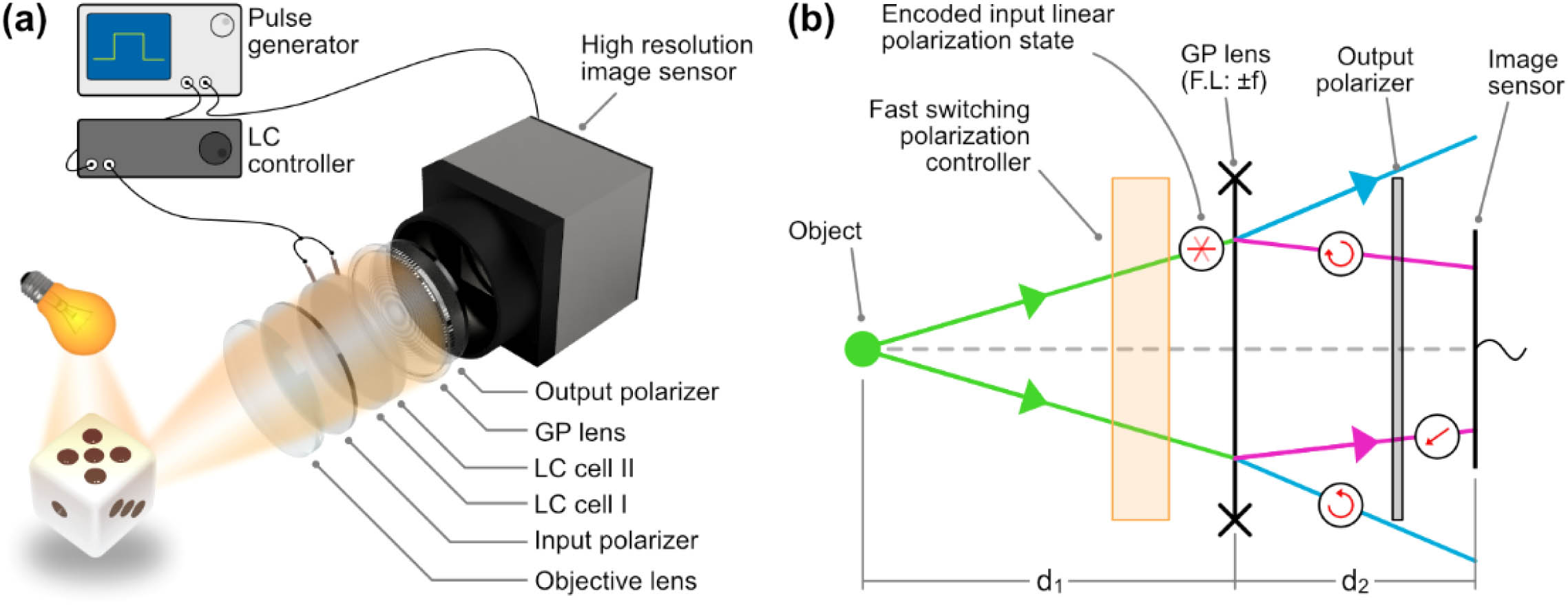
    Fig. 1. (a) Schematic of the proposed method. (b) Diagram of the simplified system with optical parameters and polarization states of each ray. F.L., focal length.
    Fast-switching polarization control unit for temporal polarization-multiplexing scheme with three steps of phase shifting. (a) Bi-stacked LC cells for three-step polarization control. (b) LPout polarization state condition according to LC cell I and LC cell II operation. (c) and (d) Dynamic response characteristics of three-step polarization switching obtained with triggering signal frequency of (c) 33 Hz and (d) 99 Hz, where the LPout state is sequentially switched as 0° → 60° → 120° → 0° and is repeatedly recycled.
    Fig. 2. Fast-switching polarization control unit for temporal polarization-multiplexing scheme with three steps of phase shifting. (a) Bi-stacked LC cells for three-step polarization control. (b) LPout polarization state condition according to LC cell I and LC cell II operation. (c) and (d) Dynamic response characteristics of three-step polarization switching obtained with triggering signal frequency of (c) 33 Hz and (d) 99 Hz, where the LPout state is sequentially switched as 0° → 60° → 120° → 0° and is repeatedly recycled.
    Recording result of the point-like source. (a) Phase-shifted interferograms. (b) Phase-angle hologram by recombining the images of (a). (c) Unwrapped phase-angle profile of (b), labeled as LC, and the ground truth hologram obtained by the manual stepwise rotation of the input polarizer at 60°, labelled as Pol. (d) Intensity profiles of the images reconstructed from both holograms Pol and LC.
    Fig. 3. Recording result of the point-like source. (a) Phase-shifted interferograms. (b) Phase-angle hologram by recombining the images of (a). (c) Unwrapped phase-angle profile of (b), labeled as LC, and the ground truth hologram obtained by the manual stepwise rotation of the input polarizer at 60°, labelled as Pol. (d) Intensity profiles of the images reconstructed from both holograms Pol and LC.
    Experimental result with two negative targets. (a) Target configuration. (b) Phase-angle representation of the obtained hologram. (c) Reconstructed image focused on target 2. (d) Reconstructed image focused on target 1. The reconstructed images are obtained from the region indicated with a dashed-red box in (b).
    Fig. 4. Experimental result with two negative targets. (a) Target configuration. (b) Phase-angle representation of the obtained hologram. (c) Reconstructed image focused on target 2. (d) Reconstructed image focused on target 1. The reconstructed images are obtained from the region indicated with a dashed-red box in (b).
    Illustration of holographic video generation process from raw interferograms to reconstructed image. The holograms are obtained from the targets shown in Fig. 4. The lateral movement of target 1 is observed through frames. The holographic video, including the phase-angle data and reconstructed image at various depth planes, is available in Visualization 1. The convolution kernel H(zr) and the circle with cross indicate the angular spectrum propagation of the complex hologram field with the distance zr. Rec., reconstructed image.
    Fig. 5. Illustration of holographic video generation process from raw interferograms to reconstructed image. The holograms are obtained from the targets shown in Fig. 4. The lateral movement of target 1 is observed through frames. The holographic video, including the phase-angle data and reconstructed image at various depth planes, is available in Visualization 1. The convolution kernel H(zr) and the circle with cross indicate the angular spectrum propagation of the complex hologram field with the distance zr. Rec., reconstructed image.
    Hologram of the reflective object. (a) Illustration of the recording scene. (b) Phase-angle map of the obtained hologram. (c) Reconstructed image, focused on the forward object. (d) Reconstructed image, focused on the backward object. 30 holograms are averaged for better visibility. The reconstructed images are cropped, where the region of interest is indicated as a red dashed box in (b).
    Fig. 6. Hologram of the reflective object. (a) Illustration of the recording scene. (b) Phase-angle map of the obtained hologram. (c) Reconstructed image, focused on the forward object. (d) Reconstructed image, focused on the backward object. 30 holograms are averaged for better visibility. The reconstructed images are cropped, where the region of interest is indicated as a red dashed box in (b).
    Illustration of holographic video generation process from raw interferograms to reconstructed image. The holograms are obtained from the targets presented in Fig. 6. The rotation of Dice 1 is observed through frames. The holographic video, including the phase-angle data and reconstructed image at various depth planes, is available in Visualization 2. Rec., reconstructed image.
    Fig. 7. Illustration of holographic video generation process from raw interferograms to reconstructed image. The holograms are obtained from the targets presented in Fig. 6. The rotation of Dice 1 is observed through frames. The holographic video, including the phase-angle data and reconstructed image at various depth planes, is available in Visualization 2. Rec., reconstructed image.
    Switching response of each LC cell: (a) LC cell I and (b) LC cell II.
    Fig. 8. Switching response of each LC cell: (a) LC cell I and (b) LC cell II.
    Dynamic response characteristics of four-step polarization switching, obtained at a triggering signal frequency of (a) 100 Hz and (b) 200 Hz. The switching on and off states for both LC cells for each polarization state (LPout) are plotted.
    Fig. 9. Dynamic response characteristics of four-step polarization switching, obtained at a triggering signal frequency of (a) 100 Hz and (b) 200 Hz. The switching on and off states for both LC cells for each polarization state (LPout) are plotted.
    LC Switching ConditionSwitching Time between LPout Transitions (ms)
    0° → 60°60° → 120°120° → 0°
    Triggering frequency for three-step phase-shifting33 Hzτ1,2=1.28τ2,3=1.18τ3,1=0.21
    99 Hzτ1,2=1.19τ2,3=1.19τ3,1=0.20
    Table 1. Switching Time Characteristics of Field-Driven LPout Transition in Three-Step Phase-Shifting Scheme Evaluated under Triggering Frequency Condition Employed for Synchronized LC Cell Operationa
    Kihong Choi, Jae-Won Lee, Jungyeop Shin, Keehoon Hong, Joongki Park, Hak-Rin Kim, "Real-time noise-free inline self-interference incoherent digital holography with temporal geometric phase multiplexing," Photonics Res. 11, 906 (2023)
    Download Citation