
Kihong Choi, Jae-Won Lee, Jungyeop Shin, Keehoon Hong, Joongki Park, Hak-Rin Kim, "Real-time noise-free inline self-interference incoherent digital holography with temporal geometric phase multiplexing," Photonics Res. 11, 906 (2023)
- Photonics Research
- Vol. 11, Issue 6, 906 (2023)
Abstract
1. INTRODUCTION
Incoherent digital holography (IDH) is a technology that acquires holograms digitally under various lighting conditions beyond those enabled by a laser [1–3]. Therefore, the advantage of acquiring holographic 3D light information can be subsequently used in more diverse applications. For instance, to the best of our knowledge, a holographic acquisition of a microbiological sample using fluorescent labeling [4,5] or an outdoor scene under sunlight [6] has not been achieved with laser-based conventional holographic interferometers. In the meantime, the problem of bias and twin-image noise, which is a classical problem of holographic interferometers because of the nature of interference, must also be solved for noise-free IDH capture. Various solutions have been suggested to address this problem not only in the field of coherent holography but also in the IDH field.
Most of the techniques to remove bias and twin-image noise from interferograms are classified according to whether real-time recording is available. Several methods, such as the off-axis configuration method [7–9], iterative phase retrieval method [10,11], and learning-based methods [12–14], have been proposed to realize real-time recording while reducing the bias and twin-image noise. Notably, the phase-shifting technique accurately eliminates the bias and twin-image noise without sacrificing the bandwidth of the image sensor, requiring additional computation time for iteration, or estimating the probable solution using a neural network. However, stepwise recording of phase-shifted interferograms is required in this method, which inevitably reduces the temporal resolution of the system.
An intuitive method to induce a phase delay is to change the propagating path lengths of two interfering beams in an interferometer. For example, in a self-interference incoherent digital holography system, one of the mirrors in the Michelson or Mach–Zehnder interferometer can be mounted on a piezoelectric transducer and actuated in a stepwise manner to sequentially induce a phase delay between the self-interfering wavefronts [6,15]. Moreover, the phase delay can be controlled both by physical distance modification and by optical path length modulation when light passes through the birefringent material. Specifically, phase-only spatial light modulators (SLMs) or liquid crystal (LC) based variable waveplates are employed in Fresnel incoherent correlation holography (FINCH) [16,17]. Simple rotation of the polarizer or waveplate also induces a phase delay between the interfering wavefronts, which is referred to as geometric phase (GP) shifting [18–20]. Particularly, the optical configuration comprises an input polarizer and a GP lens, and the output polarizer is introduced for incoherent holographic recording [21]. In this system, the relative rotation angle
Sign up for Photonics Research TOC. Get the latest issue of Photonics Research delivered right to you!Sign up now
To overcome the temporal resolution loss entailed by the phase-shifting method in holographic recording systems, modified FINCH systems with a randomly multiplexed bifocal diffractive lens [23], multiplexed checkerboard phase gratings with two SLMs [24], spatially divided diffractive lenses [25], and diffractive phase gratings with a four-segmented linear polarizer [26], have been adopted for single-shot hologram capture. Furthermore, a spatial phase multiplexing technique, called the parallel phase-shifting method, has also been developed [27,28]. Specifically, a polarized image sensor, wherein four angled (90°, 45°, 135°, and 0°) wire-grid polarizers are fabricated on each pixel, is employed in this technique. Single-shot incoherent holography is realized in FINCH-based systems with a phase-only SLM [29], birefringent lens [30], or GP lens [31–33]. As reported based on several single-shot IDH systems, using a polarized image sensor promotes real-time hologram acquisition. However, four polarized sub-pixel values must be combined into a single superpixel value to generate a complex-valued hologram free from bias and twin-image noises. This process reduces the total number of pixels both in the horizontal and vertical directions of the reconstructed image by half. Additionally, the acquirable high-frequency information near the Nyquist frequency defined by the effective pixel size and the input wavelength of light is also decreased by half. In this context, studies to minimize the pixel size in polarized image sensors have been reported, but this is challenging while simultaneously optimizing the factors underlying overall polarimetric imaging quality, such as the polarization characteristics, quantum efficiency, and angle of incidence [34].
In this paper, we propose a real-time incoherent digital holographic recording system using a fast temporally polarization-encoded phase-shifting scheme. Particularly, the fast-switching polarization controller unit comprises two bi-stacked retardation-controllable LC cells, a geometric phase lens, and polarizers. As a proof of concept, we demonstrated real-time incoherent hologram recording with a resolution of up to 20 megapixels. The frame rate of the recorded video sample is 33 Hz. This is the result of three-step sequentially phase-shifted interferograms recorded at 99 Hz using the nonpolarized image sensor. The temporal resolution of the proposed method is threefold lower than that of the parallel phase-shifting method; nevertheless, an effective recording speed of more than 30 Hz is achieved, thereby providing a reasonable temporal resolution for real-time video recording. In addition, because all components are arranged coaxially as in the optical system of a general camera, the system configuration is simple, and no mechanical movement is required for the phase shift. Consequently, stable high-speed hologram acquisition is possible. In the following section, the principle of operation of the incoherent recording system, which employs the geometric phase effect and the phase-shifting method proposed here, is described. Subsequently, a proof-of-concept experimental setup is described, and the demonstration of a real-time hologram acquisition is presented.
2. OPERATION PRINCIPLE
A. Incoherent Hologram Acquisition with Geometric Phase Shifting
A schematic of the proposed method is presented in Fig. 1. The GP lens serves as a convex lens (
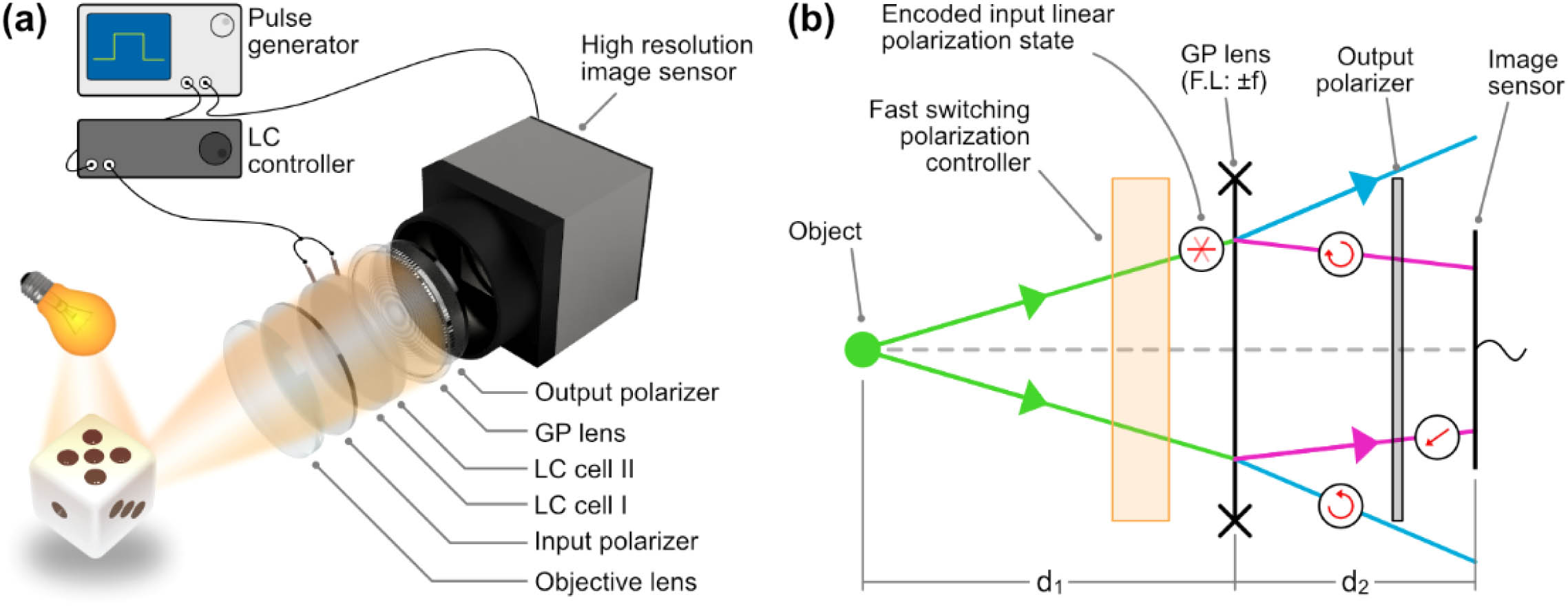
Figure 1.(a) Schematic of the proposed method. (b) Diagram of the simplified system with optical parameters and polarization states of each ray. F.L., focal length.
The wave propagation through the system can be described as beginning from the spherical wave reflected by the object or the self-illuminated by the object itself. Because such light is likely to be nonpolarized, a linear polarizer is used to define the initial polarization state before passing through the GP lens. The field immediately before the GP lens corresponds to the spherical wave diverged from the point light source with the wavelength
After further propagation toward the image sensor, corresponding to a distance
We denote the first term in Eq. (2) as
Our goal is to remove the first two terms and the last term from Eq. (3). To this end, we devise a high-speed phase-shifting technique comprising an optical circuit equivalent to an input polarizer, a half-wave plate, and an output polarizer. We refer to this scheme as the P-GP-P structure [20,21]. More specifically, the input polarization state is defined as a sequential combination of voltage values applied to two LC cells. Although the results of the mechanical rotation of the input polarizer and the driving of two LC cells are identical, the LC cell enables a high-speed polarization state change while maintaining the stability of the recording system. The details of the fast switching polarization control scheme for real-time incoherent hologram recording are described in the following subsection. The amount of phase shift of the interferogram
Here, the widely used angular spectrum method is used to retrieve the object scene from the hologram [38]. To retrieve a field
For wave number
The resultant image of the retrieved field is the intensity-valued data
B. Fast-Switching Polarization Control for Temporally-Polarization-Encoded Phase-Shifting
As described in Eqs. (4) and (5), the multisteps of the phase-shifting scheme can be employed in the holographic image reconstruction step with the IDH system with the P-GP-P structure by modulating an incident polarization state with respect to a fixed analyzer angle condition, instead of using spatially patterned analyzer sets [31]. With this temporally polarization-encoded phase-shifting approach, the holographic image resolution can be effectively enhanced, but sequentially switched polarization states must be precisely controlled to avoid phase errors during image reconstruction. In addition, the switching time between the polarization states, required for multistep phase-shifting should be as short as possible to allow sufficient image acquisition time in the camera to suppress the image noise level.
Figure 2(a) shows the fast-switching polarization controller unit employed in the P-GP-P structure for time-sequential operation of the three-step phase-shifting. The three-steps of polarization modulation can be achieved by using bi-stacked retardation-controllable LC cells [LC cell I and LC cell II in Fig. 2(a)]. In bi-stacked LC cells, each LC cell has an electrically controllable birefringence mode, which is optically operated as an
![]()
Figure 2.Fast-switching polarization control unit for temporal polarization-multiplexing scheme with three steps of phase shifting. (a) Bi-stacked LC cells for three-step polarization control. (b)
The employed LC cells exhibit a slower field-off switching response than the field-on switching response; this is because the field-on LC dynamics are driven by the field-induced dielectric torque of the LC directors, whereas the field-off LC dynamics are obtained by the cell-thickness-dependent elastic recovery, as discussed in Appendix A [42]. In our bi-stacked LC cells, the switching time (
Switching Time Characteristics of Field-Driven LPout Transition in Three-Step Phase-Shifting Scheme Evaluated under Triggering Frequency Condition Employed for Synchronized LC Cell Operation
| LC Switching Condition | Switching Time between | |||
|---|---|---|---|---|
| 0° → 60° | 60° → 120° | 120° → 0° | ||
| Triggering frequency for three-step phase-shifting | 33 Hz | |||
| 99 Hz | ||||
The total transition time required for one cycle of three-step phase-shifting is sufficiently low (
The sequential polarization control of the bi-stacked LC cells operated at triggering frequencies of 33 and 99 Hz corresponds to the holographic video frame rates of 11 and 33 Hz, respectively. For faster polarization switching (
3. EXPERIMENTAL SETUP AND RESULT
A. Experimental Setup
The proposed system comprised an objective lens, a bandpass filter, an input linear polarizer, two LC cells, a GP lens, an output linear polarizer, and a nonpolarized high-resolution image sensor. The objective lens collects the illuminating or scattering wavefronts from the object scene. The focal length and diameter of the lens are 100 mm and 1 inch, respectively. Further, the central wavelength of the bandpass filter (#65-159, Edmund Optics) is 550 nm, and the spectral bandwidth is 10 nm. The transmission axis of the input linear polarizer is aligned parallel to the ground surface to initialize the input polarization state to 0°. The LC cells (X-FPM(L)-AR, LC-Tec Displays AB) are connected to the controller (LCC-230, LC-Tec Displays AB) for triggered driving. The clear aperture of the LC cells is 50 mm in diameter. The GP lens (Beam Co.) is followed to modulate the linearly polarized input wavefront into two wavefronts with different radii of curvature, and with orthogonal circular polarization states. The focal length of the GP lens is 240 mm for the 550 nm input light, and the clear aperture is approximately 20 mm in diameter. The distance between the objective lens and the GP lens is about 80 mm. The output polarizer transforms the two orthogonal circularly polarized states into the same polarization state. Interferograms are obtained by a high-resolution and high-frame-rate nonpolarized image sensor (HB-20000SBC, Emergent Vision Technology). The resolution of the image sensor is
A function generator (33500B, Agilent) is used as a triggering source both for the image sensor and LC driver. Two LC cells are operated by the LC driver with the triggering signal from the general-purpose input (GPI) port. The image sensor is also triggered with the opto-isolated GPI port. The exposure of the image sensor starts after a 1 ms delay from the rising pulse of the triggering signal to avoid the transition state of the LC cells and to prevent jittering issues in sequential holographic image acquisitions, which are observed in the timing diagram of Figs. 2(c) and 2(d). The output signal of the function generator and the exposure start and end signals of the image sensor are observed with a connected oscilloscope (MDO34, Tektronix). At first, a stack of raw images is recorded and transferred to the main memory in real time. Then the required per-frame process is followed. The recording process of the raw images is carried out at 99 Hz with the customized software by using the application programming interface provided by the image sensor manufacturer. The elimination of the bias and twin-image noise and the reconstruction process for each frame are performed afterward using MATLAB software. The computation time for each single complex hologram and reconstructed image generation is 1.7 s, with an Intel i9-9920X processor (3.50 GHz) and 64 GB memory, without parallel processing.
B. Validation of Phase-Shifting Performance
To verify the three-step phase-shifting method with the proposed optical configuration, the 200 μm diameter fiber tip coupled with the LED source (MINTF4, Thorlabs) is recorded and reconstructed. Three phase-shifted interferograms are presented in Fig. 3(a). The resolution of each image data is
![]()
Figure 3.Recording result of the point-like source. (a) Phase-shifted interferograms. (b) Phase-angle hologram by recombining the images of (a). (c) Unwrapped phase-angle profile of (b), labeled as LC, and the ground truth hologram obtained by the manual stepwise rotation of the input polarizer at 60°, labelled as Pol. (d) Intensity profiles of the images reconstructed from both holograms Pol and LC.
The unwrapped phase profile validates that the results of the proposed phase-shifting method are almost similar to the results of the phase profile obtained by the manual rotation of the polarizer. The rms error between the two profiles is 0.009. Furthermore, the proposed method is recorded at a speed of 99 Hz without any mechanical movement. The background level around the reconstructed point in Fig. 3(d) is nearly zero, which implies that there is no remaining bias noise. Moreover, no fringe ringing artifact around the point is observed, which might be seen when the defocused twin image remains. Therefore, the elimination performance of twin-image noise of the proposed method is also validated.
C. Demonstration of the Real-Time Holographic Movie with Moving Targets
To demonstrate the fast yet robust phase-shifted hologram acquisition capability of the proposed system, the dynamic scene is recorded with two negative resolution charts in different positions. The experimental setup with two targets is illustrated in Fig. 4(a). The negative 1951 USAF (target 1) and NBS 1963A (target 2) targets are used as sample objects. The distance of each target from the system is about 78 mm and 95 mm, respectively. The targets are presented as two layers with different axial locations by employing the beam combiner, as illustrated in Fig. 4(a). A broadband halogen fiber optic illuminator (OSL2, Thorlabs) is employed as a backlight source. One of the two targets is mounted on the mechanical stage and manually translated in the vertical direction while recording the holograms. The triggering signal for both image sensor exposure and LC state change is set to 99 Hz. Therefore, the resultant frame rate of the hologram and reconstructed movie is 33 Hz. Figures 4(b)–4(d) show the obtained hologram with the phase-angle representation as well as the reconstructed images at different axial positions. The images in Figs. 4(c) and 4(d) are cropped to
![]()
Figure 4.Experimental result with two negative targets. (a) Target configuration. (b) Phase-angle representation of the obtained hologram. (c) Reconstructed image focused on target 2. (d) Reconstructed image focused on target 1. The reconstructed images are obtained from the region indicated with a dashed-red box in (b).
![]()
Figure 5.Illustration of holographic video generation process from raw interferograms to reconstructed image. The holograms are obtained from the targets shown in Fig.
The moving dice are recorded as a general object scene with the proposed system. As illustrated in Fig. 6(a), the dice toward the system (Dice 1) is mounted on an optical post and bolted on a motorized rotation stage (PRM1/MZ8, Thorlabs). The dice in the backward direction (Dice 2) is mounted on a flexible gooseneck arm and moved by tapping the arm. The distance of each dice from the system is about 100 mm and 125 mm, respectively, as shown in Fig. 6(a). The dynamic scene is recorded by rotating and moving the dice. While Dice 1 is rotating at 25 deg/s, Dice 2 is tapped by hand to express the dynamic motion. The recorded real-time hologram and reconstructed video are presented in Fig. 7 and
![]()
Figure 6.Hologram of the reflective object. (a) Illustration of the recording scene. (b) Phase-angle map of the obtained hologram. (c) Reconstructed image, focused on the forward object. (d) Reconstructed image, focused on the backward object. 30 holograms are averaged for better visibility. The reconstructed images are cropped, where the region of interest is indicated as a red dashed box in (b).
![]()
Figure 7.Illustration of holographic video generation process from raw interferograms to reconstructed image. The holograms are obtained from the targets presented in Fig.
4. DISCUSSION AND CONCLUSION
We have demonstrated a real-time self-interference IDH recording system free from bias and twin-image noise by employing the high-speed temporally polarization-encoded phase-shifting method. The three-step phase-shifting is realized by using fast polarization switching LC cells, as well as a high frame rate and a high-resolution nonpolarized image sensor. The IDH video samples are presented with two sample targets: a negative resolution target and two dice. For this demonstration, each phase-shifted interferogram is captured at 99 Hz with a resolution of more than 20 megapixels. The effective frame rate of the processed complex-valued hologram and the reconstructed video is 33 Hz. In this demonstration, the reconstruction of the video hologram is performed after the stack of raw data is acquired in real time. However, if the algorithm is optimized to reconstruct high-resolution holograms in real-time and the computational power is guaranteed, real-time high-resolution holographic streaming could be possible with the proposed method.
In general, parallel phase-shifting technology, which spatially divides and acquires phase-shifted interference fringes using a polarized image sensor, has the advantage of obtaining complex holographic data free from bias and twin image noise with a single exposure, as previously described. However, in this method, four subpixel values with phases shifted by polarizers of different angles are calculated as one complex hologram. Thus, the number of horizontal and vertical pixels of the obtained complex hologram data is reduced by half. Further, if the resolution of the optical system is sufficiently high and exceeds the Nyquist frequency of the polarized image sensor, the generated holographic fringe pattern might not be faithfully recorded, resulting in the loss of high-fidelity information. The proposed system has the advantage of real-time hologram capture while recording high-frequency fringe patterns faithfully, compared to the system using the polarized image sensor.
From a practical point of view, the polarized image sensor model among various image sensor models on the current market has a limited range of choices. Meanwhile, with the development of the latest wide-bandwidth data transmission technology, numerous image sensors with smaller pixel size and higher resolution while maintaining an acquisition speed close to or higher than 100 Hz are released on the market. Using the proposed method, it is possible to acquire high-quality holograms in real-time using a wide range of state-of-the-art image sensors that do not require additional processes such as lithography for on-chip polarizer fabrication.
As described in Section 2, the amount of the phase shift occurring in the P-GP-P optical structure depends only on the relative angle difference between the two polarizers. In particular, the GP lens, which naturally has a large dependence of the diffraction efficiency on the incident wavelength, reveals an achromatic half-wave retardation upon fabricating the lens with a stack of two chiral LC layers with opposite twist angles [44,45]. As a result, the proposed system should be able to maintain phase-shifting performance uniformly over a wide wavelength range and is supposed to use the entire red, green, and blue pixel aperture of the employed color image sensor to capture full-color holographic information of the object scene. In practice, because the polarization-encoding performance of the LC cells constituting the polarization control unit used in this demonstration is guaranteed only near the designed wavelength, the bandwidth of the incident light is inevitably limited to 10 nm through filtering, and only the green pixel aperture contributes to the hologram image recording. However, the dispersion properties of the polarization control LC module employed for the temporal switching of polarization-encoded phase shifting can be effectively suppressed by adopting achromatic optics designs with additional field-switching LC layers assembled with optically distributed optic axes [46–48]. Thus, the proposed temporal polarization multiplexing scheme is operable while maintaining phase-shifting performance uniformly over a wide wavelength range for the promising full-color IDH system, which will be developed in future studies.
APPENDIX A: MEASUREMENT OF SWITCHING RESPONSE OF EACH LC CELL
The dynamic transmittance curves are measured by setting each LC cell between the crossed polarizers, where the optic axis of the LC cell at the field-off state is 45° with respect to the transmission axes of the polarizers. The LC-driving signal used for this evaluation is a square wave, operated at an amplitude of
![]()
Figure 8.Switching response of each LC cell: (a) LC cell I and (b) LC cell II.
APPENDIX B: MEASURMENT OF CHARACTERISTICS OF FOUR-STEP POLARIZATION SWITCHING WITH BI-STACKED LC CELLS
Figure
Characteristics of Switching Time between LPout Transitions in Four-Step Phase-Shifting According to the Triggering Frequency Condition
| LC Switching Condition | Switching Time between | ||||
|---|---|---|---|---|---|
| 0° → 135° | 135° → 45° | 45° → 90° | 90° → 0° | ||
| Triggering frequency for four-step phase-shifting | 100 Hz | ||||
| 200 Hz | |||||
![]()
Figure 9.Dynamic response characteristics of four-step polarization switching, obtained at a triggering signal frequency of (a) 100 Hz and (b) 200 Hz. The switching on and off states for both LC cells for each polarization state (
References
[6] M. K. Kim. Full color natural light holographic camera. Opt. Express, 21, 9636-9642(2013).
[38] T.-C. Poon, J.-P. Liu. Introduction to Modern Digital Holography: With MATLAB(2014).
[39] S. Kumar. Liquid Crystals: Experimental Study of Physical Properties and Phase Transitions(2000).
[41] G. R. Fowles. Introduction to Modern Optics(1989).
[42] D.-K. Yang, S.-T. Wu. Fundamentals of Liquid Crystal Devices(2014).


Set citation alerts for the article
Please enter your email address

© Copyright 2018-2021 | Chinese Laser Press. All Rights Reserved 沪ICP备15018463号-20