• Laser & Optoelectronics Progress
  • Vol. 55, Issue 4, 042201 (2018)
Zhongyu Chen1、2, Shaoyun Yin1, Xiuhui Sun1, Haibo Jiang1, and Chunlei Du1、*
Author Affiliations
  • 1 Integrated Optoelectronic Technology Center, Chongqing Institute of Green and Intelligent Technology, Chinese Academy of Sciences, Chongqing 400714, China
  • 2 University of Chinese Academy of Sciences, Beijing 100049, China
  • show less
    DOI: 10.3788/LOP55.042201 Cite this Article Set citation alerts
    Zhongyu Chen, Shaoyun Yin, Xiuhui Sun, Haibo Jiang, Chunlei Du. Design of Fly-Eye Lens with Free-Form Surface Used in Parallel Light Exposure Machine with Large Area and High Uniformity[J]. Laser & Optoelectronics Progress, 2018, 55(4): 042201 Copy Citation Text show less
    (a) Optical system of exposure machine; (b) smoothing principle of fly-eye lens
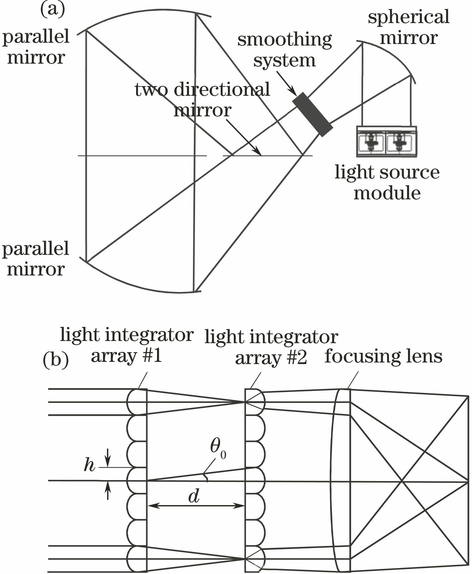
    Fig. 1. (a) Optical system of exposure machine; (b) smoothing principle of fly-eye lens
    Target surface spot when the integrator is (a) lens and (b) spherical mirror, respectively
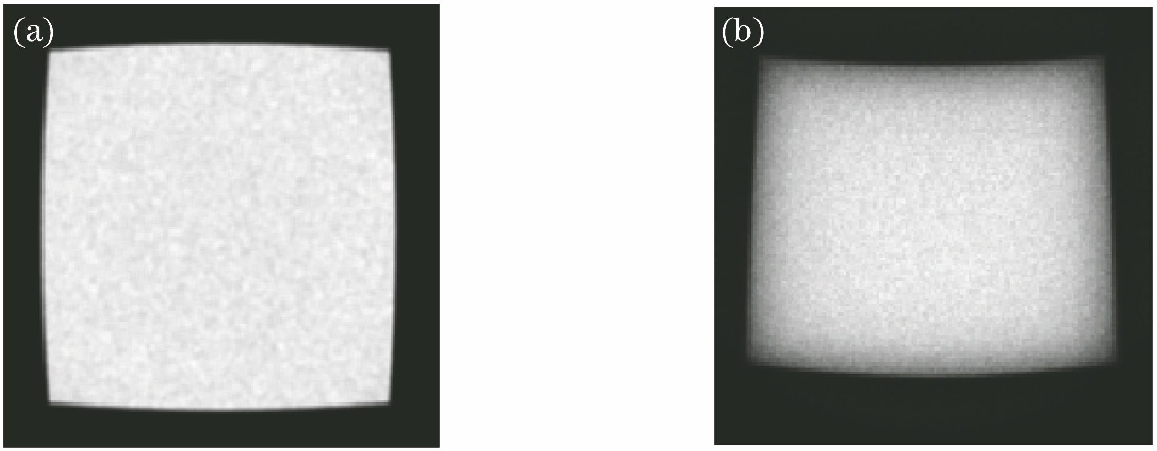
    Fig. 2. Target surface spot when the integrator is (a) lens and (b) spherical mirror, respectively
    Target surface spot with parallel light incidence at single angle. (a) 0°; (b) 14°
    Fig. 3. Target surface spot with parallel light incidence at single angle. (a) 0°; (b) 14°
    Light path diagram of exposure machine
    Fig. 4. Light path diagram of exposure machine
    Illuminance distribution of target surface spot
    Fig. 5. Illuminance distribution of target surface spot
    Sketch diagram of light and vector relation
    Fig. 6. Sketch diagram of light and vector relation
    (a) Contour lines of free-form surface and sphere; (b) schematic diagram of free-form surface; (c) free-form surface lens array model
    Fig. 7. (a) Contour lines of free-form surface and sphere; (b) schematic diagram of free-form surface; (c) free-form surface lens array model
    (a) Spot and (b) illuminance distribution curve of target surface with traditional fly-eye lens
    Fig. 8. (a) Spot and (b) illuminance distribution curve of target surface with traditional fly-eye lens
    (a) Spot and (b) illuminance distribution curve of target surface with free-form surface fly-eye lens
    Fig. 9. (a) Spot and (b) illuminance distribution curve of target surface with free-form surface fly-eye lens
    PositionUniformityPositionUniformityPositionUniformityPositionUniformityPositionUniformity
    (-40,-40)0.9568(-20,-40)0.9551(0,-40)0.9610(20,-40)0.9623(40,-40)0.9598
    (-40,-20)0.9609(-20,-20)0.9614(0,-20)0.9588(20,-20)0.9668(40,-20)0.9652
    (-40,0)0.9608(-20,0)0.9619(0,0)0.9574(20,0)0.9595(40,0)0.9593
    (-40,20)0.9623(-20,20)0.9575(0,20)0.9590(20,20)0.9616(40,20)0.9548
    (-40,40)0.9643(-20,40)0.9609(0,40)0.9613(20,40)0.9552(40,40)0.9557
    Table 1. Relationship change between uniformity of target surface spot and beam center
    Zhongyu Chen, Shaoyun Yin, Xiuhui Sun, Haibo Jiang, Chunlei Du. Design of Fly-Eye Lens with Free-Form Surface Used in Parallel Light Exposure Machine with Large Area and High Uniformity[J]. Laser & Optoelectronics Progress, 2018, 55(4): 042201
    Download Citation