
Heng Zuo, Xi Zhang, Yong Zhang. Segmented Mirror Edge Sensors Based on Equal Thickness Interference[J]. Acta Optica Sinica, 2021, 41(12): 1212002
- Acta Optica Sinica
- Vol. 41, Issue 12, 1212002 (2021)
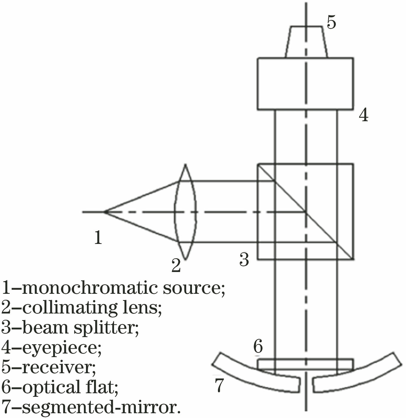
Fig. 1. Edge error detection structure of segmented-mirror based on equal thickness interference
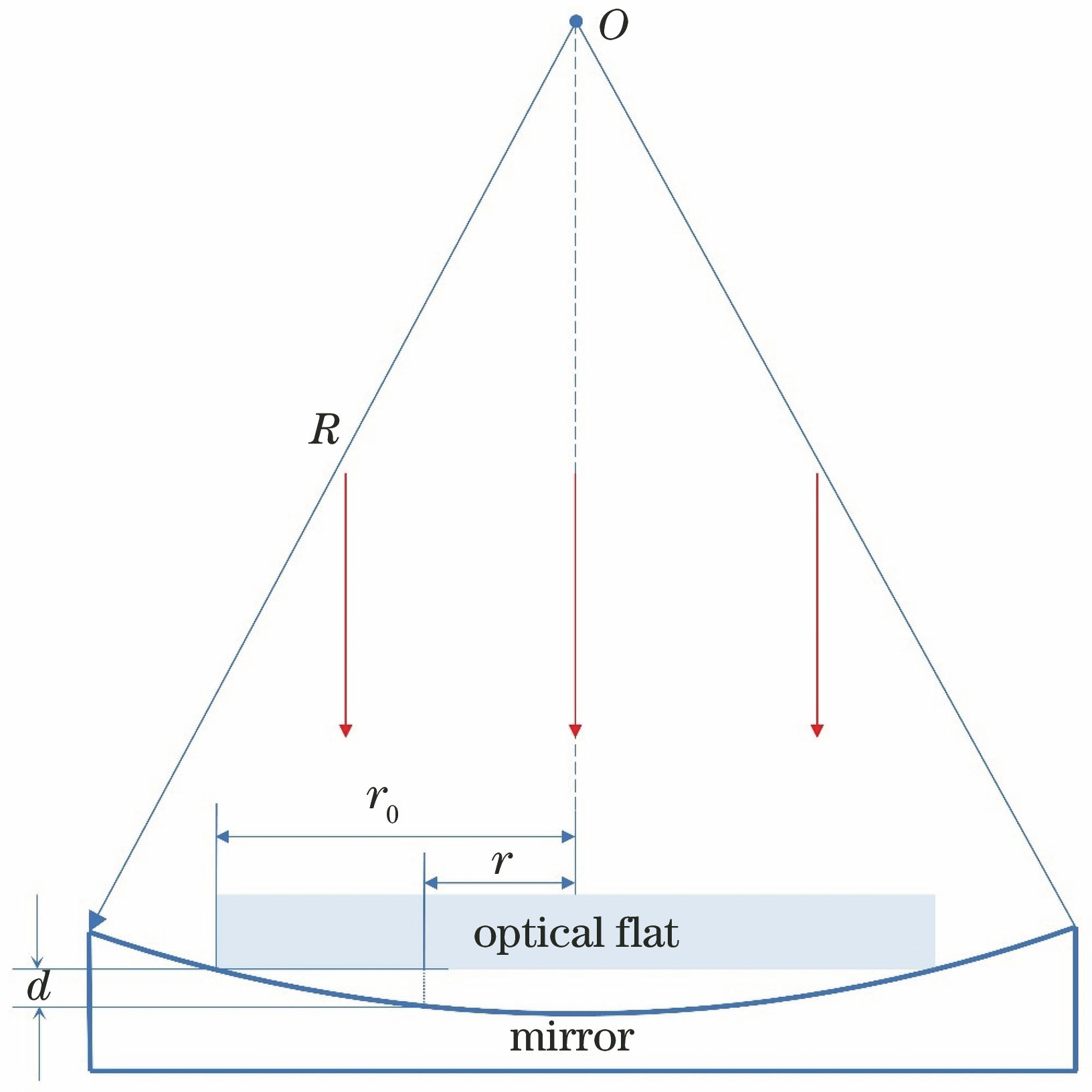
Fig. 2. Segmented-mirror measurement based on equal thickness interference principle
Fig. 3. Light intensity distribution of two sub-mirrors without segment error
Fig. 4. Light intensity distribution when the two sub-mirrors have relative errors. (a) x-axis tip error; (b) y-axis tilt error; (c) piston error
Fig. 5. Gray value liner fitting on the center line of Newton ring. (a) Newton ring corresponding to the left sub-mirror; (b) Newton ring corresponding to the right sub-mirror with 35 nm piston error
Fig. 6. Change of radius of Newton ring with piston error
Fig. 7. Changes in the position of the optical flat and the equivalent aperture after the piston error of the two mirrors. (a) No error between the two sub-mirrors; (b) a piston error between the two sub-mirrors
Fig. 8. Hough test results when there is a tilt error between the two sub-mirrors. (a) 2-1 Hough test result; (b) improved Hough concentric circle test result
Fig. 9. Interference image of equal thickness when the installation translation error of optical flat is 3 mm
Fig. 10. Interference fringe images of equal thickness when there is an overall tilt error. (a) Existing a tilt error of 10″ along the x-axis; (b) existing a tilt error of 10″ along the y-axis
|
Table 1. Parameters for the edge detection system composed of two segmented-mirrors
|
Table 2. Change in the center of the circle when the tilt error is 0.02″
|
Table 3. Change of the fringe parameters with or without pointing error (σTip=0.02″)
|
Table 4. Comparison of the designed sensor and electrical sensor

Set citation alerts for the article
Please enter your email address
© Copyright 2018-2021 | Chinese Laser Press. All Rights Reserved 沪ICP备15018463号-20