• Photonics Research
  • Vol. 11, Issue 11, 1880 (2023)
Xinhao Jiang1, Yunyun Ji1,2,*, Fei Fan1,3,4, Songlin Jiang1..., Zhiyu Tan1, Huijun Zhao1, Jierong Cheng1 and Shengjiang Chang1,3,5|Show fewer author(s)
Author Affiliations
  • 1Institute of Modern Optics, Nankai University, Tianjin 300350, China
  • 2Tianjin Key Laboratory of Micro-scale Optical Information Science and Technology, Tianjin 300350, China
  • 3Tianjin Key Laboratory of Optoelectronic Sensor and Sensing Network Technology, Tianjin 300350, China
  • 4e-mail: fanfei@nankai.edu.cn
  • 5e-mail: sjchang@nankai.edu.cn
  • show less
    DOI: 10.1364/PRJ.501047 Cite this Article Set citation alerts
    Xinhao Jiang, Yunyun Ji, Fei Fan, Songlin Jiang, Zhiyu Tan, Huijun Zhao, Jierong Cheng, Shengjiang Chang, "Arbitrary terahertz chirality construction and flexible manipulation enabled by anisotropic liquid crystal coupled chiral metasurfaces," Photonics Res. 11, 1880 (2023) Copy Citation Text show less
    (a) Schematic diagram of the metadevice for different chiral responses at different operating frequencies when the LC optical axis is along the x, y, and z axes. (b) Optical microscopy image of the metasurface. (c) Placement of the bilayer metasurface and geometrical parameters of the meta-atom. (d) Schematic diagram of the metadevice configuration. (e) Schematic diagram of the THz-TDPS system.
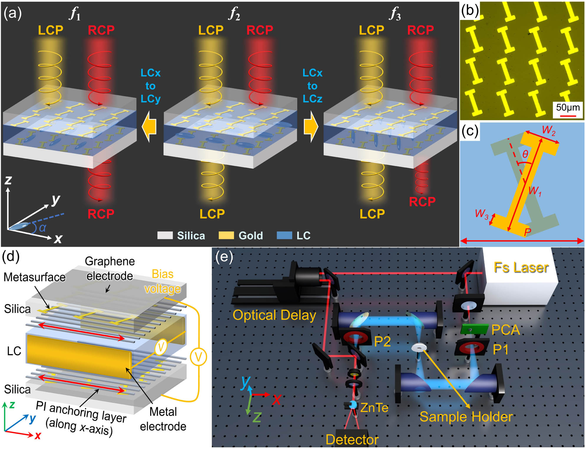
    Fig. 1. (a) Schematic diagram of the metadevice for different chiral responses at different operating frequencies when the LC optical axis is along the x, y, and z axes. (b) Optical microscopy image of the metasurface. (c) Placement of the bilayer metasurface and geometrical parameters of the meta-atom. (d) Schematic diagram of the metadevice configuration. (e) Schematic diagram of the THz-TDPS system.
    CD map as a function of THz frequency and LC rotational angle α when (a) θ=0°, (b) θ=90°, (c) θ=40°, and (d) θ=65°.
    Fig. 2. CD map as a function of THz frequency and LC rotational angle α when (a) θ=0°, (b) θ=90°, (c) θ=40°, and (d) θ=65°.
    Spatial mirror symmetry of the bilayer anisotropic metasurface with different θ: 0°, 90°, 0°–90°, when the LC is (a) absent and (b) present. The CD spectra under different configurations with different θ: (c) θ=0°, (d) θ=90°, (e) θ∈(0°,90°). (f) The CD spectra of the metadevice with respect to θ, when the LC optical axis is along the x, y, and z axes.
    Fig. 3. Spatial mirror symmetry of the bilayer anisotropic metasurface with different θ: 0°, 90°, 0°–90°, when the LC is (a) absent and (b) present. The CD spectra under different configurations with different θ: (c) θ=0°, (d) θ=90°, (e) θ(0°,90°). (f) The CD spectra of the metadevice with respect to θ, when the LC optical axis is along the x, y, and z axes.
    For rotating the LC optical axis in the x–y plane: the experimental transmission spectra of (a) TLL, (b) TRL, (c) TRR, and (d) TLR with the bias voltage increasing from 0 to 100 V when illuminated by LCP and RCP waves.
    Fig. 4. For rotating the LC optical axis in the xy plane: the experimental transmission spectra of (a) TLL, (b) TRL, (c) TRR, and (d) TLR with the bias voltage increasing from 0 to 100 V when illuminated by LCP and RCP waves.
    Tuning the LC optical axis in the x–y plane. (a) The experimental Co-CD spectra as the bias voltage increases from 0 to 100 V. (b) The simulated Co-CD spectra with the LC optical axis turned from 0° (x axis) to 90° (y axis). The frequency position and CD intensity of (c) Peak 1 and (d) Peak 2 at different bias voltages. (e) The polarization state of the output wave at 0.69 THz under LCP incidence and (f) that at 0.94 THz under RCP incidence as the bias voltage increases from 0 to 100 V.
    Fig. 5. Tuning the LC optical axis in the xy plane. (a) The experimental Co-CD spectra as the bias voltage increases from 0 to 100 V. (b) The simulated Co-CD spectra with the LC optical axis turned from 0° (x axis) to 90° (y axis). The frequency position and CD intensity of (c) Peak 1 and (d) Peak 2 at different bias voltages. (e) The polarization state of the output wave at 0.69 THz under LCP incidence and (f) that at 0.94 THz under RCP incidence as the bias voltage increases from 0 to 100 V.
    For rotating the LC optical axis in the x–z plane: the experimental transmission spectra of (a) TLL, (b) TRL, (c) TRR, and (d) TLR with the bias voltage increasing from 0 to 80 V when illuminated by LCP and RCP waves.
    Fig. 6. For rotating the LC optical axis in the xz plane: the experimental transmission spectra of (a) TLL, (b) TRL, (c) TRR, and (d) TLR with the bias voltage increasing from 0 to 80 V when illuminated by LCP and RCP waves.
    Tuning the LC optical axis in the x–z plane. (a) The experimental Co-CD spectra as the bias voltage increases from 0 to 80 V. (b) The simulated Co-CD spectra with the LC optical axis turned from 0° (x axis) to 90° (z axis). The frequency position and CD intensity of (c) Peak 1 and (d) Peak 2 at different bias voltages. (e) The polarization state of the output wave at 0.6 THz under LCP incidence and (f) that at 0.92 THz under RCP incidence as the bias voltage increases from 0 to 80 V.
    Fig. 7. Tuning the LC optical axis in the xz plane. (a) The experimental Co-CD spectra as the bias voltage increases from 0 to 80 V. (b) The simulated Co-CD spectra with the LC optical axis turned from 0° (x axis) to 90° (z axis). The frequency position and CD intensity of (c) Peak 1 and (d) Peak 2 at different bias voltages. (e) The polarization state of the output wave at 0.6 THz under LCP incidence and (f) that at 0.92 THz under RCP incidence as the bias voltage increases from 0 to 80 V.
    Experimental and simulated (a) transmission and (b) phase difference of the monolayer anisotropic metasurface. (c) Experimental transmission spectra of the 300 μm thick LC layer. (d) The absorption coefficient of ordinary light and extraordinary light.
    Fig. 8. Experimental and simulated (a) transmission and (b) phase difference of the monolayer anisotropic metasurface. (c) Experimental transmission spectra of the 300 μm thick LC layer. (d) The absorption coefficient of ordinary light and extraordinary light.
    For pure bilayer chiral metasurfaces without LC: (a) theoretical Co-CD spectrum when θ=0°, 40°, and 90°, (b) simulated CD spectra with respect to θ.
    Fig. 9. For pure bilayer chiral metasurfaces without LC: (a) theoretical Co-CD spectrum when θ=0°, 40°, and 90°, (b) simulated CD spectra with respect to θ.
    Electric distribution of the metasurfaces under different conditions: (a) at 0.69 THz when LC optical axis is along the y axis, (b) at 0.92 THz when the LC optical axis is in the x–y plane and at an angle of 26° from the x axis, (c) at 0.945 THz when LC optical axis is along the x axis, (d) at 0.885 THz when the LC optical axis is in the x–z plane and at an angle of 40° from the x axis, and (e) at 0.725 THz when the LC optical axis is along the z axis.
    Fig. 10. Electric distribution of the metasurfaces under different conditions: (a) at 0.69 THz when LC optical axis is along the y axis, (b) at 0.92 THz when the LC optical axis is in the xy plane and at an angle of 26° from the x axis, (c) at 0.945 THz when LC optical axis is along the x axis, (d) at 0.885 THz when the LC optical axis is in the xz plane and at an angle of 40° from the x axis, and (e) at 0.725 THz when the LC optical axis is along the z axis.
    For rotating the LC optical axis in the x–y plane. The (a) PEA and (b) PRA of the output wave at 0.69 THz under LCP incidence, and the (c) PEA and (d) PRA of the output wave at 0.94 THz under RCP incidence as the bias voltage increases from 0 to 100 V.
    Fig. 11. For rotating the LC optical axis in the xy plane. The (a) PEA and (b) PRA of the output wave at 0.69 THz under LCP incidence, and the (c) PEA and (d) PRA of the output wave at 0.94 THz under RCP incidence as the bias voltage increases from 0 to 100 V.
    For rotating the LC optical axis in the x–z plane. The (a) PEA and (b) PRA of the output wave at 0.6 THz under LCP incidence, and the (c) PEA and (d) PRA of the output wave at 0.92 THz under RCP incidence as the bias voltage increases from 0 to 80 V.
    Fig. 12. For rotating the LC optical axis in the xz plane. The (a) PEA and (b) PRA of the output wave at 0.6 THz under LCP incidence, and the (c) PEA and (d) PRA of the output wave at 0.92 THz under RCP incidence as the bias voltage increases from 0 to 80 V.
    Xinhao Jiang, Yunyun Ji, Fei Fan, Songlin Jiang, Zhiyu Tan, Huijun Zhao, Jierong Cheng, Shengjiang Chang, "Arbitrary terahertz chirality construction and flexible manipulation enabled by anisotropic liquid crystal coupled chiral metasurfaces," Photonics Res. 11, 1880 (2023)
    Download Citation