Chiral metasurfaces integrated with active materials can dynamically control the chirality of electromagnetic waves, making them highly significant in physics, chemistry, and biology. Herein, we theoretically proposed a general and feasible design scheme to develop a chiral metadevice based on a bilayer anisotropic metasurface and a monolayer liquid crystal (LC), which can construct and flexibly manipulate arbitrary terahertz (THz) chirality. When the twist angle between the anisotropic axes of two metasurfaces is not 0°, the spatial mirror symmetry of the chiral metadevice is broken, resulting in a strong THz chiral response. In addition, the introduction of anisotropic LCs not only enhances the chiral response of the metadevice but also induces the flipping modulation and frequency tunability of the chirality. More importantly, by optimizing the , we can flexibly design the arbitrary chiral response and the operating frequency of chirality, thereby promoting the emergence of various chiral manipulation devices. The experimental results show that the maximum circular dichroism can reach at 0.94 THz and flip to 28 dB at 0.69 THz by rotating the LC optical axis from the to axis, with the maximum operating frequency tunable range of . We expect this design strategy can create new possibilities for the advancement of active THz chiral devices and their applications, including chiral spectroscopy, molecular recognition, biosensing, and fingerprint detection.
1. INTRODUCTION
Chirality is a geometric property of an object that cannot be overlapped with its mirror image through any translation or rotation [1,2]. It is ubiquitous in nature and has promising applications in optics [3], biology [4], chemistry [5], and medical and life sciences [6]. When interacting with left- and right-circularly polarized (LCP and RCP) waves, chiral objects exhibit distinct optical responses [7], that is, the chiroptical effect—circular dichroism (CD) and optical activity (OA), which refers to the differences in transmittance and phase delay to LCP and RCP waves, respectively [8,9]. Most biomolecules are chiral, and their vibrational and rotational energy levels are usually located in the terahertz (THz) band (0.1–10 THz, ) [10,11]. Therefore, the research on THz chirality has attracted wide interest in the fields of biochemistry and medicine. In recent studies, THz chirality techniques have been employed to gain a better understanding and identification of some chiral biomolecules [12,13]. However, most natural chiral media suffer from weak chiroptical effects due to the weak light–matter interaction between them and electromagnetic waves, which hinders their practical applications in various systems [14].
Fortunately, the advent of chiral metasurfaces provides a solution for the weak chirality of natural media. Chiral metasurfaces are a novel optical element comprised of a series of subwavelength elements, offering an effective avenue to achieve artificial chirality [15]. Their chiroptical effects are several orders of magnitude larger than naturally occurring chiroptical effects, and these chiroptical effects can be flexibly and artificially designed by adjusting and optimizing the size and period of structural units (i.e., meta-atom). For instance, Gansel et al. demonstrated a chiral device through the construction of a 3D gold helix structure [16]. Zhu et al. achieved chirality by constructing a 2D planar dielectric metasurface with a gammadion structure [17]. Furthermore, extrinsic chirality can also be realized when the incident beam is obliquely directed onto the metasurface [18]. Benefiting from the strong chirality, designability, and easy integration, chiral metasurfaces have received much attention in many fields, including biosensing [19], chiral light imaging [20], and communication. Although chiral metasurfaces can enhance chiroptical effects, the chiral response of most chiral metadevices is fixed once fabricated, and the lack of dynamically tunable chirality poses challenges for these devices in complex scenarios.
To address these issues, researchers have proposed chiral metasurfaces with variable structures, allowing for adjustable chiroptical effects through the mechanical deformation of the structures [21]. However, such active chiral metadevices are often limited by their bulky volume and complex regulation methods. Alternatively, active chiroptical effects can also be achieved by combining chiral metasurfaces with active materials, including semiconductors, graphene, phase change materials [22–24], and so on. These materials can respond to external stimuli and alter the chiroptical effect of the metadevices. However, the chirality of such chiral metadevices typically originates from the chiral metasurface rather than active materials, which only enables chirality switching and flipping modulation at fixed frequencies. These devices have great potential in polarization imaging [25], circular polarization detection, chiral spectroscopy [26], and other applications. However, there is an urgent need to develop active THz chiral devices with flexible designs and tunable control capabilities to meet the application requirements related to THz chirality.
Sign up for Photonics Research TOC. Get the latest issue of Photonics Research delivered right to you!Sign up now
Liquid crystals (LCs), as an active material, exhibit broadband optical anisotropy that can be controlled by external fields, e.g., thermal, optical, electric, and magnetic. Due to the controllable anisotropic axis of LCs, many researchers have introduced LCs in the development of active THz manipulation devices [27], such as active THz beam manipulation devices [28,29], active THz waveplates [30], and active THz polarization manipulation devices [31–34]. Furthermore, LCs can also be used to build active THz chiral devices. For example, Zhang et al. utilized cholesteric LC, which possesses inherent chirality, to make an active THz chiral device with temperature-dependent chirality [35]. Zhao et al. combined an anisotropic dielectric metasurface with LCs to realize tunable THz chiral devices [36]. Currently, LC-based active THz chiral devices have achieved intensity modulation of chiral response. However, to develop devices with better performance and richer chiral modulation functions, especially those capable of frequency modulation of chiral response, further research is still needed.
In this work, we propose a strategy for achieving tunability of chiral response in the aspect of intensity and operating frequency. The bilayer anisotropic metasurface exhibits an intrinsic weak chiroptical effect due to its mirror asymmetry when the twist angle between the two anisotropic axes is neither 0° nor 90°. Then, we introduced LCs into the bilayer metasurface to form a chiral metadevice. The addition of tunable anisotropic LCs further enhances the mirror asymmetry of the metadevice, enabling it to achieve a tunable strong chiral response. More importantly, by selecting a specific twist angle for the two metasurface layers, it can be ensured that the metadevice exhibits different spatial structures when the LC optical axis points in different directions, resulting in different operating frequencies of the chirality. Therefore, this metadevice can achieve flipping modulation and frequency tunability of chiral response as the LC optical axis rotates in 3D space and can flexibly design the arbitrary chiral response and the operating frequency of chirality by optimizing the twist angle . This intuitive and feasible strategy holds promising potential for various chirality-related applications.
2. PRINCIPLE AND DESIGN
A. Theoretical Analysis
The active THz chiral metadevice is composed of a bilayer anisotropic metal metasurface and an anisotropic LC layer. For a single anisotropic metasurface, its transmission matrix can be written as [37] where the fast/slow axis of the metasurface is assumed to be parallel to the axis when . and denote the transmission coefficient for the -linearly polarized (-LP) and -LP components, and is the phase difference between the two LP components. The transmission matrix of the LC layer under the LP basis can be written as follows: where is the rotational angle between the long axis of the LC and the axis. and denote the transmission coefficient for extraordinary light (e-light) and ordinary light (o-light). The phase difference between the e-light and o-light can be calculated by , where is the thickness of the LC layer, and refer to the ordinary refractive index and extraordinary refractive index of the LC, respectively, and represents the wavelength.
In our design, the angle between the anisotropic axis of the upper (lower) metasurface and the axis is (), that is, the twist angle between the anisotropic axes of two metasurfaces is ; thus, the total transmission matrix of the composite device based on metasurface-LC-metasurface under the LP basis is
To clearly identify the transmission properties of our metadevice, Eq. (3) can be transferred to a matrix under the CP basis vector:
Thus, the total transmission matrix under the CP basis can be written as where
The Co-CD can be calculated by where and are the transmission intensity expressed in dB.
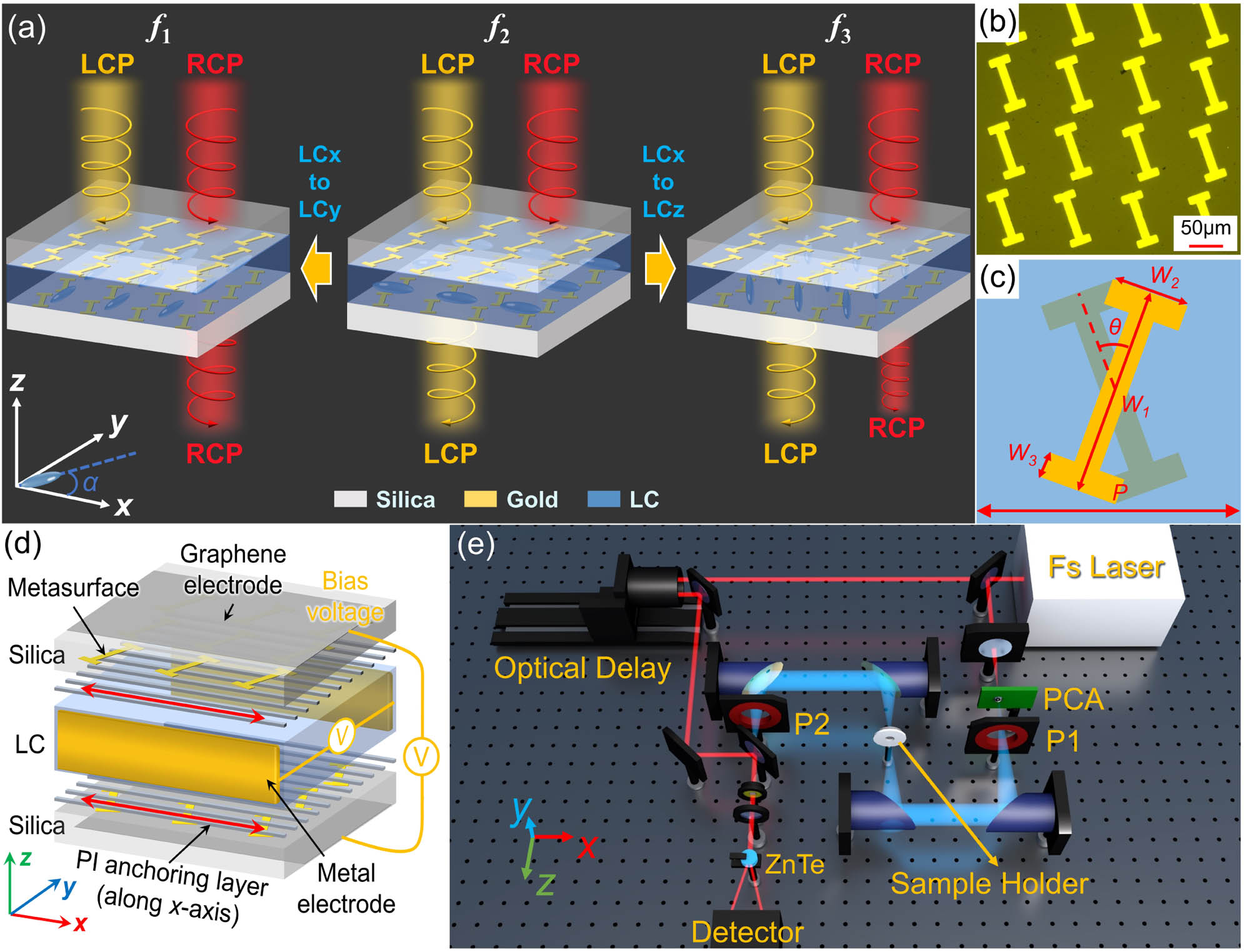
Figure 1(a) presents the schematic diagram of the metadevice based on metasurface-LC-metasurface with the LC optical axis along different directions (, , and axes). Figure 1(b) is the optical microscopy image of the metasurface, which illustrates the meta-atom of the anisotropic metal metasurface used in this work. The meta-atom is designed as a slanted I-shaped structure whose anisotropic axis is along its long axis, resulting in a notable uniaxial anisotropic response in a specific frequency range [Appendix A, Figs. 8(a) and 8(b)]. Figure 1(c) shows the placement of the bilayer metasurface and the geometrical parameters of the meta-atom, where μ, μ, μ, and μ in the and axes, and the twist angle between the two anisotropic axes of the bilayer metasurface is . The LC used in the metadevice is a high-birefringence nematic LC (, HTD-028200) from Jiangsu Hecheng Technology Co., Ltd., which exhibits uniaxial anisotropic properties within a broad THz frequency range, and the rotational angle between the long axis of the LC and the axis is . Its phase-transition temperature from crystal state to LC state () and from LC state to isotropic state () is and 103°C, respectively, and its viscosity coefficient () is (25°C). The optimized LC thickness of 300 μm is determined by comprehensively considering the coupling effect of the two metasurfaces and the influence of LC anisotropy on the entire metadevice. The transmission characteristics of the LC material can be seen in Figs. 8(c) and 8(d) in Appendix A. As shown in Fig. 1(d), the PI anchoring layers can anchor the LC molecules along the axis, and the LC molecules can be gradually tuned to the axis (or axis) when an increasing bias voltage is applied to the metal electrodes in the axis (or the graphene electrodes in the axis). All samples are measured using the THz time-domain polarization spectroscopy (THz-TDPS) system in Fig. 1(e) (Appendix D).
Figure 1.(a) Schematic diagram of the metadevice for different chiral responses at different operating frequencies when the LC optical axis is along the , , and axes. (b) Optical microscopy image of the metasurface. (c) Placement of the bilayer metasurface and geometrical parameters of the meta-atom. (d) Schematic diagram of the metadevice configuration. (e) Schematic diagram of the THz-TDPS system.
According to Eqs. (5) and (6), we can obtain the four CP states (i.e., , , , and , where the first/second subscript indicates the output/input CP component), and then calculate the CD map as a function of THz frequency and . Owing to the negligible difference between the two cross-CP states (i.e., and ), we only focus on the two Co-CP states in the following discussions. Then, we discuss the influence of and on the chirality of the metadevice, and several significant cases are outlined below: 1) when both anisotropic axes of the bilayer metasurface are parallel to the axis (i.e., ), , indicating there is no chirality in the metadevice regardless of of the LC optical axis [Fig. 2(a)]; 2) when their anisotropic axes are perpendicular (i.e., ), , and the CD of the metadevice is reversed as the LC optical axis rotates from 0° ( axis) to 90° ( axis) [Fig. 2(b)]. Therefore, the chirality of the device achieves dynamic flipping modulation as the LC optical axis changes, but this chiral manipulation is limited to fixed frequencies. This is because the metadevice with LC rotation angles of and is always enantiomers when , thereby leading to an opposite chiral response of the metadevice in these two states. 3) When , the composite structures also possess chirality (i.e., ). If , the CD also undergoes a reversal as the LC optical axis rotation angle gradually changes from 0° to 90° [Fig. 2(c)]. More interestingly, the operating frequency of the strong CD also changes during the variation process of . The reason for this phenomenon is that the metadevices with the LC rotation angle of and any other arbitrary angle do not exhibit an enantiomeric relationship, resulting in different CD operating frequencies with different . The same phenomena can be found in the case of , as shown in Fig. 2(d); thus, the device not only achieves the intensity control of the CD but also enables the dynamic control of its operating frequency in this case. As a consequence, we can flexibly design various chiral manipulation devices by optimizing the twist angle .
Figure 2.CD map as a function of THz frequency and LC rotational angle when (a) , (b) , (c) , and (d) .
B. Geometric Symmetry Analysis and Parameter Optimization
Based on the definition of geometric chirality, we further investigate the chiral response of our metadevice with and without LC under different twisted angles . First, with the absence of LC, the spatial mirror symmetry of geometric structures is as shown in Fig. 3(a); Figs. 3(c)–3(e) show the CD spectra of the bilayer anisotropic metasurface with different . When the twisted angle is 0° or 90°, the bilayer metasurface structure can be superposed onto its mirror image by translation and rotation, which means that the structure is mirror symmetry in the propagation direction. Moreover, the CD value of 0 also indicates that the device is achiral in the above two cases, as shown by the solid yellow line in Figs. 3(c) and 3(d). When , the bilayer metasurface cannot coincide with its mirror image through any translation or rotation, indicating that the mirror symmetry of the device is broken, thus exhibiting a chiral response. As shown by the yellow solid line in Fig. 3(e), the device has a weak chiral response at two frequencies.
Figure 3.Spatial mirror symmetry of the bilayer anisotropic metasurface with different : 0°, 90°, 0°–90°, when the LC is (a) absent and (b) present. The CD spectra under different configurations with different : (c) , (d) , (e) . (f) The CD spectra of the metadevice with respect to , when the LC optical axis is along the , , and axes.
Second, with the presence of LC, Fig. 3(b) shows the mirror symmetry of the three cases when the angle is 0°, 90°, and 0°–90°, respectively. When , it can be found that, regardless of the LC optical axis orientation, the metadevice is always mirror symmetry. We show the CD spectra in Fig. 3(c) when the LC optical axis is along the and axes, and their CD values of 0 further confirm that the metadevice is achiral at this time. When , the metadevice cannot be coincident with its mirror image when the LC optical axis is along the and axes, giving rise to a chiral response. Moreover, the metadevice exhibits an enantiomeric relationship under the above-mentioned two LC states [38–40], resulting in an exactly opposite CD response, as shown in Fig. 3(d). When belongs to 0°–90°, the composite structure always fails to coincide with its mirror image when the LC optical axis is at any angle in 3D space; thus, the composite structure is always mirror asymmetric, resulting in a more flexible manipulation of chiral response. Moreover, the metadevice exhibits a diastereomeric relationship under the cases of the LC optical axis along the and axes (or any other LC director orientation), which induces chirality at different frequencies, as shown in Fig. 3(e). These conclusions are consistent with the theoretical analysis mentioned in Section 2.A. Furthermore, the introduction of the anisotropic LC further increases the mirror symmetry breaking of the metadevice, thus enhancing its chirality and resulting in a larger CD value. Figure 3(f) illustrates the simulated Co-CD spectra of the composite structure with different when the LC optical axis is along the , , and axes (details about numerical simulation can be seen in Appendix C). The frequency and intensity of the CD change with the variation of . After comprehensive consideration, 40° is chosen as the optimal value of . As can be seen, the maximum CD of the metadevice occurs at different frequencies when LC optical axis is along the , , and axes. It is evident that the metadevice supports chiral responses at different frequencies and possesses active tuning characteristics.
3. RESULTS AND DISCUSSION
A. Active THz Chirality and Polarization in Metadevice by Tuning the LC Optical Axis in the Plane
Experiments are conducted to verify the proposed theoretical design scheme. To enable the rotation of the LC optical axis in the plane, the LC molecules are initially anchored in the axis by two polyimide (PI) anchoring layers, and a tunable bias voltage along the axis is applied. Then, we obtain the THz response of the metadevice when the LC optical axis gradually turns from the axis to the axis by using the THz-TDPS system. Figure 4 shows the experimental transmission spectra of the four CP components. As shown in Figs. 4(a) and 4(c), the transmission spectra of the two Co-CP components (i.e., and ) under the same bias voltage are different, and this difference in transmission can be continuously tuned by changing the applied bias voltage, indicating a tunable chiral response. As the applied bias voltage increases from 0 to 100 V, the transmission intensity of gradually decreases at around 0.69 THz, accompanied by a redshift of the resonant frequency, while the transmission intensity of remains almost unchanged around this frequency. Meanwhile, the transmission intensity of remains almost unchanged at approximately 0.94 THz, while that of gradually increases with a rise of the bias voltage, accompanied by a redshift of the resonant frequency. In Figs. 4(b) and 4(d), the difference in transmission intensity between the cross-CP components (i.e., and ) is small and is also less affected by the bias voltage, indicating that the metadevice does not possess cross-polarization transmission asymmetry (i.e., cross-polarization chirality).
Figure 4.For rotating the LC optical axis in the plane: the experimental transmission spectra of (a) , (b) , (c) , and (d) with the bias voltage increasing from 0 to 100 V when illuminated by LCP and RCP waves.
To better reflect the chiral response and dynamic manipulation characteristics of the metadevice, Fig. 5(a) illustrates the experimental Co-CD spectra. As shown in Fig. 5(a), when the bias voltage switches from 0 to 100 V, the Co-CD flips from a significantly negative value at 0.85–1.05 THz to a significantly positive value at 0.64–0.73 THz, reaching the maximum value of 28 dB at 0.69 THz (Peak 1) and at 0.94 THz (Peak 2), respectively. Figures 5(c) and (d) further show the frequency position and CD intensity of Peak 1 and Peak 2 at different bias voltages. In Fig. 5(c), as the bias voltage increases from 0 to 100 V, the frequency position of Peak 1 shifts from 0.75 to 0.69 THz, while the CD intensity rises from 4 to 28 dB. Meanwhile, the frequency position of Peak 2 shifts from 0.94 to 0.78 THz, accompanied by a change in CD intensity from to , as shown in Fig. 5(d). When the CD of a chiral metadevice exceeds a specific threshold, it can be deemed to exhibit a chiral response, and we contend that the metadevice demonstrates practical chirality when the absolute value of CD exceeds 5 dB in this work. Using this criterion, Peak 1 exhibits an operating frequency tunable range of , while Peak 2 has an operating frequency tunable range of . Figure 5(b) displays the corresponding simulated Co-CD, in which the LC optical axis turns from 0° ( axis) to 90° ( axis). The simulated CD intensity and frequency shift exhibit a similar trend as observed in the experimental results, confirming the reliable active chirality of the metadevice. The slight deviations between experiments and simulations arise from the following points: (i) the error introduced in the fabrication of the device; (ii) the absorption and dispersion of LCs in the experiment are not considered in the simulation; (iii) the inherent noise brought by the experimental environment. The metadevice also possesses the capability to dynamically manipulate the polarization state of the output wave (see quantitative description of the polarization state in Appendix F). Here, Figs. 5(e) and 5(f) illustrate the variations in the polarization state of the output wave at a specific frequency with increasing bias voltage under LCP and RCP incidence, respectively. In Fig. 5(e), when the LCP wave is incident, the output wave at 0.69 THz changes from a left-handed elliptically polarized wave to a nearly pure LP wave and then to a nearly pure RCP wave as the bias voltage increases from 0 to 100 V. In Fig. 5(f), under the RCP incidence, the output wave at 0.94 THz transforms from a nearly pure LCP wave to a nearly pure LP wave and eventually to a right-handed elliptically polarized wave with increasing bias voltage.
Figure 5.Tuning the LC optical axis in the plane. (a) The experimental Co-CD spectra as the bias voltage increases from 0 to 100 V. (b) The simulated Co-CD spectra with the LC optical axis turned from 0° ( axis) to 90° ( axis). The frequency position and CD intensity of (c) Peak 1 and (d) Peak 2 at different bias voltages. (e) The polarization state of the output wave at 0.69 THz under LCP incidence and (f) that at 0.94 THz under RCP incidence as the bias voltage increases from 0 to 100 V.
B. Active THz Chirality and Polarization in Metadevice by Tuning the LC Optical Axis in the Plane
We further discuss the influence of the LC optical axis variation in the plane on the chiral response of the metadevice. In this situation, a graphene conductive layer is coated on the silica substrates of the metadevice as a THz transparent electrode in the direction, and a tunable bias voltage is applied to the graphene electrodes. Figure 6 shows the experimental transmission spectra of the four CP components. In Fig. 6(a), the transmission intensity of at around 0.72 THz gradually decreases with the increasing bias voltage, accompanied by a redshift of the resonant frequency, whereas that of remains almost constant at this frequency. In Fig. 6(c), a strong resonance of at 0.94 THz is observed when the bias voltage is 0 V. As the bias voltage increases, the resonant frequency point of experiences a noticeable redshift, accompanied by a decrease in resonance intensity. The transmission intensity of , on the other hand, remains almost the same at this frequency. As for the cross-CP components shown in Figs. 6(b) and 6(d), it is obvious that they remain constant despite variations in the applied bias voltage. The difference between and indicates that the metadevice exhibits a chiral response and can be tuned when the LC optical axis varies in the plane.
Figure 6.For rotating the LC optical axis in the plane: the experimental transmission spectra of (a) , (b) , (c) , and (d) with the bias voltage increasing from 0 to 80 V when illuminated by LCP and RCP waves.
To explore the chiral response of the metadevice when the LC optical axis varies in the plane, the experimental and simulated Co-CD spectra of the metadevice are as shown in Figs. 7(a) and 7(b), respectively. In Fig. 7(a), the experimental Co-CD exhibits two significant CD peaks (i.e., Peak 1 and Peak 2). The changes in the corresponding frequency position and peak intensity of Peak 1 and Peak 2 as bias voltage varies are shown in Figs. 7(c) and 7(d). When the bias voltage increases from 0 to 80 V, the frequency position of Peak 1 gradually moves from 0.75 to 0.72 THz, while its intensity gradually rises from 4 to 14 dB. Meanwhile, the frequency position of Peak 2 redshifts from 0.94 to 0.86 THz, and the peak intensity gradually changes from to . As a result, the operating frequency tunable range of Peak 1 and Peak 2 is and , respectively. The simulated Co-CD spectra depicted in Fig. 7(b) demonstrate a similar trend to the experimental results when the LC optical axis turns from 0° ( axis) to 90° ( axis). Dynamic polarization conversion can also be achieved by rotating the LC optical axis in the plane, as shown in Figs. 7(e) and 7(f). Figure 7(e) illustrates the change in the output polarization state at 0.6 THz under LCP incidence, where the output wave remains as a left-handed elliptically polarized wave, while the azimuth angle continuously varies with increasing bias voltage. In Fig. 7(f), the output wave at 0.92 THz under RCP incidence transitions from an almost pure LCP wave to a left-handed elliptically polarized wave with increasing bias voltage.
Figure 7.Tuning the LC optical axis in the plane. (a) The experimental Co-CD spectra as the bias voltage increases from 0 to 80 V. (b) The simulated Co-CD spectra with the LC optical axis turned from 0° ( axis) to 90° ( axis). The frequency position and CD intensity of (c) Peak 1 and (d) Peak 2 at different bias voltages. (e) The polarization state of the output wave at 0.6 THz under LCP incidence and (f) that at 0.92 THz under RCP incidence as the bias voltage increases from 0 to 80 V.
According to the experimental and simulation results, our metadevice with the structure of metasurface-LC-metasurface breaks the mirror symmetry in the propagation direction and thus possesses intrinsic chirality. With the change of the LC optical axis, the composite metadevice exhibits different spatial geometric chirality, resulting in flexible manipulation of the chiral response in the aspect of intensity and frequency. As the -axis voltage gradually increases from 0 to 100 V, the CD peak near 0.94 THz in Fig. 5 undergoes a redshift accompanied by a decrease in intensity, while the CD peak near 0.75 THz undergoes a redshift accompanied by an increase in intensity. The tuning phenomenon of the LC optical axis rotating in the plane is similar to the case, as shown in Fig. 7. The difference is that the tuning range of CD in the aspect of intensity and operating frequency is different in the above two scenarios. In short, the above two scenarios can achieve different active manipulation of THz chirality, making the manipulation of this chiral metadevice more flexible.
It is significant to note that we only consider and collect the main pulse signal that is directly transmitted, while ignoring other secondary signals that are transmitted through multiple reflections of the cavity structure in theoretical analysis, simulation, and experiments. Therefore, the chirality of this metadevice only stems from the breaking of spatial mirror symmetry rather than mode splitting caused by Fabry–Perot resonance. Compared with the previous studies, the proposed design scheme has flexible designability and stronger regulatory ability. In our design scheme, the proposed metadevice is constructed from a three-layer structure. By designing the geometric parameters of the anisotropic metasurface, the twist angle of the anisotropic axis of the bilayer anisotropic metasurface, and the thickness of the LC layer, the desired arbitrary chirality can be customized in a certain frequency range.
4. CONCLUSION
In summary, a theoretical design scheme for achieving arbitrary THz chirality construction and its dynamic manipulation is proposed based on bilayer anisotropic metal metasurface integrating anisotropic LCs. To realize the THz chiral response, it is necessary to construct a chiral metadevice with mirror symmetry breaking, which requires that the twist angle between the anisotropic axes of two metasurfaces should not be 0°. Moreover, the introduction of anisotropic LC not only participates in the chirality construction but also brings dynamic manipulation characteristics to the metadevice, enabling it to have flipping modulation and operating frequency tunability of chirality. Theoretical analysis shows that, by adjusting the twist angle, we can flexibly design the THz chiral metadevice mentioned above to generate arbitrary chiral responses and operating frequencies of chirality. When tuning the LC optical axis in the plane, the experimental CD of the metadevice can be flipped from at 0.94 THz to 28 dB at 0.69 THz and the CD peak has a maximum operating frequency tunable range of . When tuning the LC optical axis in the plane, the operating frequency of the CD peak can be continuously tuned in the range of . This theoretical design scheme has a broad application prospect in the fields of THz chirality sensing, complex THz chirality manipulation, biomolecular recognition, and other fields.
APPENDIX A: OPTICAL RESPONSE OF MONOLAYER METASURFACE AND LC
Figures 8(a) and 8(b) demonstrate the pronounced uniaxial anisotropic response (i.e., the transmission and phase of LP waves along the short and long axes of the anisotropic meta-atom show significant differences) of our anisotropic metal metasurface at 0.7–1.1 THz. Figures 8(c) and 8(d) show the transmission spectra of the 300 μm thick LC layer and the absorption coefficient of the LC we used in the experiment, respectively.
Figure 8.Experimental and simulated (a) transmission and (b) phase difference of the monolayer anisotropic metasurface. (c) Experimental transmission spectra of the 300 μm thick LC layer. (d) The absorption coefficient of ordinary light and extraordinary light.
APPENDIX B: THEORETICAL ANALYSIS AND SIMULATED CD SPECTRA OF THE BILAYER CHIRAL METASURFACE WITHOUT LC
We also carry out theoretical analysis for pure bilayer chiral metasurfaces without LC. The middle layer is an isotropic medium of air in this case, and we can obtain the CD spectrum by Eqs. (5) and (6) when the twist angle of the anisotropic axes of the bilayer metasurface is 0°, 40°, and 90° in Fig. 9(a). It can be seen that, when the twist angle is 0° and 90°, the CD of the device is 0, which is consistent with the geometric chiral analysis in Section 2.B. Then, we show the simulated CD spectra for pure bilayer chiral metasurfaces without LC with the change of the twist angle , as shown in Fig. 9(b). It can be seen that the twist angle of 40° is not the optimal value in this case, indicating that the addition of LC affects the chiral response of the device. The reason is that the anisotropic LC layer participates in the chirality construction of the overall metadevice, and its geometric chirality can also be flexibly controlled by rotating the LC optical axis. In short, LC affects the excitation and manipulation of THz chirality in composite devices, which is essential for optimizing the twist angle.
Figure 9.For pure bilayer chiral metasurfaces without LC: (a) theoretical Co-CD spectrum when , 40°, and 90°, (b) simulated CD spectra with respect to .
All numerical simulations were conducted using the finite-difference time-domain method. The periodic boundary is applied in the and directions, and the boundaries in the direction are set as perfectly matched layers. The period in the and directions is 100 μm, and the propagation distance of light in the direction is set to 4 mm. The glass permittivity is set to 4. In the simulation, the material setting of the metasurface is set as a Drude model (gold) with plasmon frequency and damping constant . The simulation employed high-accuracy mesh settings and the minimum mesh step in this simulation model is set to μ and μ, which is much smaller than the wavelength of THz wave and the size of the structure. The extraordinary and ordinary refractive indices ( and ) of the LCs in the simulation are set to 1.9 and 1.6, respectively. Further, we obtained the LCP and the RCP wave source by superimposing two orthogonal LP wave sources with a phase difference of .
APPENDIX D: EXPERIMENTAL SYSTEM AND DATA PROCESSING
A THz-TDPS system is used in our experiments, and the system is added with two additional THz polarizers based on a standard four-parabolic mirror THz-TDS system. THz pulses are generated by a GaAs photoconductive antenna, which is excited by a femtosecond laser. The excitation source is a Ti:sapphire laser with a 75 fs duration of 80 MHz repetition rate working at 800 nm. The polarization direction of the excited THz wave is along the axis. A ZnTe crystal is used for the electro-optic sampling probe. All experiments are carried out at room temperature with a humidity of less than 30%. The two metal metasurfaces utilized in the experiment are coated with a PI anchoring film, with the anchoring direction being along the axis, so that the LC optical axis is initially arranged along the axis.
All the CP transmission coefficients (i.e., , , , and ) of the device can be calculated by utilizing the four linear transmission coefficients (i.e., , , , and ) measured by rotating the two THz polarizers to in the THz-TDPS system. The transmission matrix of a chiral device can be calculated as follows [41,42]:
The four CP components can be obtained by .
By calculating the terminal trajectory equation of the electric vector , we can accurately depict the polarization state of the output wave clearly and concisely, as follows [43]: where the phase difference . The polarization state of the output wave can be described quantitatively by polarization ellipticity angle (PEA) and polarization rotation angle (PRA), which can be calculated by where tan . If the PEA is 0°, the output wave will be an LP wave, and it will turn to a pure LCP wave or a pure RCP wave when the PEA reaches or , respectively.
APPENDIX E: ELECTRIC FIELD DISTRIBUTION OF METASURFACES
In our metadevice, the change of the LC optical axis can alter the spatial mirror symmetry of the composite metadevice, leading to a frequency shift in chiral response. Moreover, the variation of the LC optical axis can also affect the coupling effect of the bilayer metasurface, thus affecting the chiral intensity of the device. To better explain the mechanism of the device, we draw the electromagnetic distribution of the bilayer metasurface at different frequencies under the illumination of LCP and RCP waves, as shown in Fig. 10. The chiral response is mainly caused by the different coupling effects between the THz waves of two conjugated spin states and the metasurfaces, which are affected by the anisotropy of the intermediate LC layer. Here, we present several representative cases. Figure 10(a) shows the case where the device is at 0.69 THz, and the LC optical axis is in the axis. By comparing the electric field distribution of the upper and lower metasurfaces with the incidence of RCP and LCP waves, we can find that the local electric field of the upper and lower metasurfaces for LCP incidence is much stronger than for RCP incidence, which indicates the strong interaction between the LCP wave and the device and, hence, a lower transmittance. Therefore, the transmittance of the LCP wave is lower than that of the RCP wave in this situation, giving rise to a strong chiral response of the device. When the LC optical axis is in the plane, and the angle between it and the axis is 26°, the local electric fields of the metasurfaces at 0.92 THz are as shown in Fig. 10(b). In this case, the local electric field of the upper and lower metasurfaces for RCP incidence is stronger than that for LCP incidence, which indicates the transmittance of the RCP wave is lower than that of the LCP wave, and the chiral response caused by this case is opposite of the case in Fig. 10(a). The cases shown in Figs. 10(c) and 10(d) are similar to the case shown in Fig. 10(b), and the situation in Fig. 10(e) is similar to that in Fig. 10(a).
Figure 10.Electric distribution of the metasurfaces under different conditions: (a) at 0.69 THz when LC optical axis is along the axis, (b) at 0.92 THz when the LC optical axis is in the plane and at an angle of 26° from the axis, (c) at 0.945 THz when LC optical axis is along the axis, (d) at 0.885 THz when the LC optical axis is in the plane and at an angle of 40° from the axis, and (e) at 0.725 THz when the LC optical axis is along the axis.
Figure 11 illustrates the variations in PEA and PRA at a specific frequency of the output wave under CP incidence when tuning the LC optical axis in the plane. For LCP incidence, the PEA at 0.69 THz first changes from 21° at 0 V to 0° at around 30 V and then increases in reverse to at 100 V [Fig. 11(a)]. Meanwhile, in Fig. 11(b), the PRA exhibits a value of 39° at 0 V, reaching a minimum of 16° at 40 V and subsequently increasing to 30° at 100 V. Similarly, Figs. 11(c) and 11(d) show the change of the output polarization state at 0.94 THz for RCP incidence. As the bias voltage increases from 0 to 100 V, the PEA gradually changes from 44° to , while the PRA decreases from 55° to 23° and then increases to 47°.
Figure 11.For rotating the LC optical axis in the plane. The (a) PEA and (b) PRA of the output wave at 0.69 THz under LCP incidence, and the (c) PEA and (d) PRA of the output wave at 0.94 THz under RCP incidence as the bias voltage increases from 0 to 100 V.
Figure 12.For rotating the LC optical axis in the plane. The (a) PEA and (b) PRA of the output wave at 0.6 THz under LCP incidence, and the (c) PEA and (d) PRA of the output wave at 0.92 THz under RCP incidence as the bias voltage increases from 0 to 80 V.