• Advanced Photonics
  • Vol. 4, Issue 6, 064001 (2022)
Zhaoyang Sun1, Yang Li1、*, Benfeng Bai1、*, Zhendong Zhu2, and Hongbo Sun1、*
Author Affiliations
  • 1Tsinghua University, State Key Laboratory of Precision Measurement and Instruments, Department of Precision Instrument, Beijing, China
  • 2National Institute of Metrology, Beijing, China
  • show less
    DOI: 10.1117/1.AP.4.6.064001 Cite this Article Set citation alerts
    Zhaoyang Sun, Yang Li, Benfeng Bai, Zhendong Zhu, Hongbo Sun. Silicon nitride-based Kerr frequency combs and applications in metrology[J]. Advanced Photonics, 2022, 4(6): 064001 Copy Citation Text show less
    Chip-scale frequency comb and its applications. (a) Under a continuous wave (CW) pump, a microring resonator generates a Kerr frequency comb. (b) Dual-comb for ultrafast ranging. © 2018 American Association for the Advancement of Science (AAAS). (c) Kerr frequency comb for astronomical spectrograph calibration. © 2019 Nature Publishing Group. (d) Dual-comb spectroscopy. © 2014 Nature Publishing Group. (e) Two interlocked combs for timing. © 2019 Optica Publishing Group. (f) Frequency combs for communications. © 2017 Nature Publishing Group. (g) Frequency combs for ultralow noise frequency synthesis. © 2018 Nature Publishing Group. Reproduced with permission.1" target="_self" style="display: inline;">1–6" target="_self" style="display: inline;">–6
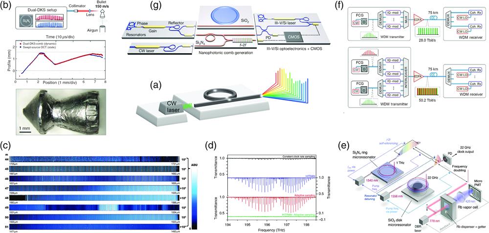
    Fig. 1. Chip-scale frequency comb and its applications. (a) Under a continuous wave (CW) pump, a microring resonator generates a Kerr frequency comb. (b) Dual-comb for ultrafast ranging. © 2018 American Association for the Advancement of Science (AAAS). (c) Kerr frequency comb for astronomical spectrograph calibration. © 2019 Nature Publishing Group. (d) Dual-comb spectroscopy. © 2014 Nature Publishing Group. (e) Two interlocked combs for timing. © 2019 Optica Publishing Group. (f) Frequency combs for communications. © 2017 Nature Publishing Group. (g) Frequency combs for ultralow noise frequency synthesis. © 2018 Nature Publishing Group. Reproduced with permission.16" target="_self" style="display: inline;">6
    The generation process of Kerr frequency combs. When the pump power couples into the resonator, the primary comb lines arise by MI first. Along the tuning process, cascaded FWM is generated, resulting in more comb lines. Finally, the comb is formed after further tuning. © 2016 De Gruyter. Reproduced with permission.40" target="_self" style="display: inline;">40
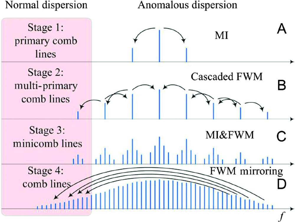
    Fig. 2. The generation process of Kerr frequency combs. When the pump power couples into the resonator, the primary comb lines arise by MI first. Along the tuning process, cascaded FWM is generated, resulting in more comb lines. Finally, the comb is formed after further tuning. © 2016 De Gruyter. Reproduced with permission.40
    Dispersion engineering broadens the comb spectrum. (a) The anomalous dispersion regimes correspond to waveguides with different cross-section dimensions. (b) Dispersive waves induce spectrum broadening. (c) Dispersive waves of waveguides with different cross-section dimensions. © 2017 Optica Publishing Group. Reproduced with permission.43" target="_self" style="display: inline;">43
    Fig. 3. Dispersion engineering broadens the comb spectrum. (a) The anomalous dispersion regimes correspond to waveguides with different cross-section dimensions. (b) Dispersive waves induce spectrum broadening. (c) Dispersive waves of waveguides with different cross-section dimensions. © 2017 Optica Publishing Group. Reproduced with permission.43
    Simulations and steady solutions of LLE with the corresponding experimental results. (a) Experimental (top) and simulation (bottom) results under different detuning. © 2015 John Wiley & Sons. Steady curves in the (b) anomalous and (c) normal dispersion regions. © 2014 American Physical Society (APS). Reproduced with permission.26" target="_self" style="display: inline;">26,46" target="_self" style="display: inline;">46
    Fig. 4. Simulations and steady solutions of LLE with the corresponding experimental results. (a) Experimental (top) and simulation (bottom) results under different detuning. © 2015 John Wiley & Sons. Steady curves in the (b) anomalous and (c) normal dispersion regions. © 2014 American Physical Society (APS). Reproduced with permission.26,46
    Different fabrication methods for SiN microrings. (a) Subtractive process. (b) Photonic Damascene process. (c) Formation of cracks and bubbles. (d) Comparison between the devices fabricated by (a) (left) and (b) (right). © 2018 IEEE. (e) Analysis of sidewall roughness with and without the reflow technique. © 2018 Optica Publishing Group. Reproduced with permission.14" target="_self" style="display: inline;">14,99" target="_self" style="display: inline;">99
    Fig. 5. Different fabrication methods for SiN microrings. (a) Subtractive process. (b) Photonic Damascene process. (c) Formation of cracks and bubbles. (d) Comparison between the devices fabricated by (a) (left) and (b) (right). © 2018 IEEE. (e) Analysis of sidewall roughness with and without the reflow technique. © 2018 Optica Publishing Group. Reproduced with permission.14,99
    Measurement setups for Kerr frequency combs. I, OSA for spectrum measurement; II, oscilloscope for transmission power monitoring; III, ESA for RF noise monitoring; IV, auto correlation or FROG for pulse measurement.
    Fig. 6. Measurement setups for Kerr frequency combs. I, OSA for spectrum measurement; II, oscilloscope for transmission power monitoring; III, ESA for RF noise monitoring; IV, auto correlation or FROG for pulse measurement.
    Characteristics of Kerr frequency combs. (a) Transmission spectrum along the tuning of the pump laser. (b) Spectra corresponding to different regions in (a). (c) RF noise spectra corresponding to different regions in (a). © 2014 Nature Publishing Group. Reproduced with permission.25" target="_self" style="display: inline;">25
    Fig. 7. Characteristics of Kerr frequency combs. (a) Transmission spectrum along the tuning of the pump laser. (b) Spectra corresponding to different regions in (a). (c) RF noise spectra corresponding to different regions in (a). © 2014 Nature Publishing Group. Reproduced with permission.25
    Measurement of dispersion. (a) Calibration schemes based on fiber comb (I) and MZI (II). (b) Measurement results of MZI-based calibration scheme [(II) in (a)]; red line shows the MZI’s interference while green line shows resonance. © 2017 Xu Yi PHD thesis. Reproduced with permission.55" target="_self" style="display: inline;">55
    Fig. 8. Measurement of dispersion. (a) Calibration schemes based on fiber comb (I) and MZI (II). (b) Measurement results of MZI-based calibration scheme [(II) in (a)]; red line shows the MZI’s interference while green line shows resonance. © 2017 Xu Yi PHD thesis. Reproduced with permission.55
    Dual-comb spectroscopy. (a) Schematic of dual-comb spectroscopy. (b) Time-domain interference. (c) Beating of two frequency combs, corresponding to (b).
    Fig. 9. Dual-comb spectroscopy. (a) Schematic of dual-comb spectroscopy. (b) Time-domain interference. (c) Beating of two frequency combs, corresponding to (b).
    Dual-comb ranging. (a) Schematic and principle of dual-comb ranging. (b) Distance measured experimentally. (c) Allan deviation of measurement. © 2018 American Association for the Advancement of Science (AAAS). (d) Schematic of parallel LIDAR. (e) Principle of FMCW. © 2020 Nature Publishing Group. Reproduced with permission.121" target="_self" style="display: inline;">121,157" target="_self" style="display: inline;">157
    Fig. 10. Dual-comb ranging. (a) Schematic and principle of dual-comb ranging. (b) Distance measured experimentally. (c) Allan deviation of measurement. © 2018 American Association for the Advancement of Science (AAAS). (d) Schematic of parallel LIDAR. (e) Principle of FMCW. © 2020 Nature Publishing Group. Reproduced with permission.121,157
    MaterialRefractive indexn2 (m2W1)Q factor
    MgF267691.37(79)×10211×109
    CaF270721.431.2×10201×1011
    BaF2731.472.85×10205×108
    SrF2741.431.76×10201×109
    Silica16,66,751.453×10206.7×108
    Hydex761.71.15×10191×106
    SiOxNy771.51.3×108
    SiOxCy76,781.71.15×10191.2×106
    Si3N4792.02.5×10193.7×107
    Diamond802.381.3×10191×106
    Silicon81,823.475×10185.9×105
    Ta2O5832.056.2×10193.2×106
    AlN842.122.3×10199.3×105
    LiNbO385872.211.8×10192.2×106
    AlGaAs88,893.32.7×10171.5×106
    GaP413.057.8×10193×105
    Table 1. Different materials for generating Kerr frequency combs.
    Zhaoyang Sun, Yang Li, Benfeng Bai, Zhendong Zhu, Hongbo Sun. Silicon nitride-based Kerr frequency combs and applications in metrology[J]. Advanced Photonics, 2022, 4(6): 064001
    Download Citation