Modern information networks are built on hybrid systems working at disparate optical wavelengths. Coherent interconnects for converting photons between different wavelengths are highly desired. Although coherent interconnects have conventionally been realized with nonlinear optical effects, those systems require demanding experimental conditions, such as phase matching and/or cavity enhancement, which not only bring difficulties in experimental implementation but also set a narrow tuning bandwidth (typically in the MHz to GHz range as determined by the cavity linewidth). Here, we propose and experimentally demonstrate coherent information transfer between two orthogonally propagating light beams of disparate wavelengths in a fiber-based optomechanical system, which does not require phase matching or cavity enhancement of the pump beam. The coherent process is demonstrated by interference phenomena similar to optomechanically induced transparency and absorption. Our scheme not only significantly simplifies the experimental implementation of coherent wavelength conversion but also extends the tuning bandwidth to that of an optical fiber (tens of THz), which will enable a broad range of coherent-optics-based applications, such as optical sensing, spectroscopy, and communication.
Light at different wavelengths has distinct features in light–matter interactions. Those distinct strengths have been exploited in separate optical systems for various applications, such as ultrasensitive sensing, spectroscopy, metrology, and communication.1–4 To leverage the strengths of those separate systems and develop optical information networks with increased size and complexity, it is often required to convert photons coherently between disparate wavelengths. The conventional wisdom on wavelength conversion relies on materials’ optical nonlinearities.5–7 Recently, enabled by advanced nanofabrication techniques, a more efficient scheme exploiting photon–phonon interaction in optomechanical structures8–13 has been intensively explored for achieving coherent wavelength conversion.14–19 With controllable photon–phonon interaction, the photon conversion efficiency can potentially reach unity by constructing an optomechanical dark state.20 To date, the strong and tailorable coupling between photons and phonons has greatly facilitated coherent information conversion among optics, mechanics, and other physical degrees of freedom in both the classical and quantum regimes.21–28 Despite great success, the existing wavelength conversion systems using either nonlinear optical effects or photon–phonon interaction usually require strict phase matching between traveling photons and phonons17–19 or strong cavity enhancement of resonant photons at both wavelengths.14–16,18,20 These stringent requirements add to difficulties and limitations in experimental implementation, such as limited selection of operating wavelengths and narrow operating bandwidths. As a result, many traditional schemes for wavelength conversion are impractical because of the incompatibility with other wavelength-dependent optical components. Therefore, strategies without the above difficulties and limitations for universal coherent conversion of photons between disparate optical systems are being sought.
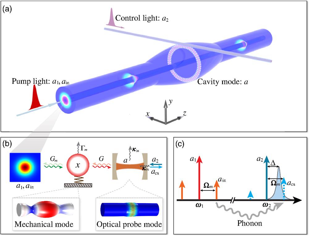
Here, we experimentally demonstrate coherent optical wavelength conversion between two orthogonally propagating light beams of disparate wavelengths in a fiber-based optomechanical system, as shown in Fig. 1(a). In the system, a high-quality mechanical mode serves as a coherent link between the pump and probe photons at different wavelengths. The information carried by the pump light traveling in the fiber core is coherently transferred to the probe light of a cavity mode traveling orthogonally in the fiber cladding. Since coherent signal conversion via the photon–phonon interaction can be identified by the phenomena of optomechanically induced transparency (OMIT) or electro-optomechanically induced transparency (EOMIT),15,25,26 here we prove coherent signal conversion between different wavelengths by demonstrating the symbolic interference phenomenon similar to electro-optomechanically induced transparency and absorption, which is enabled by the broadband nonresonant pump photons. The conversion efficiency reflected by the transparency or absorption strength is highly tunable by the pump strength and pump modulation phase. Compared with previous methods, our scheme features the following advantages. Owing to the high quality factors of the mechanical mode () and the optical probe mode (), the pump light that actuates the mechanical motion does not need cavity enhancement or phase matching, thus avoiding the previously mentioned difficulties and limitations. The tuning bandwidth of the pump light is now the working wavelength range of the optical fiber, which is typically tens of terahertz and a 4-order-of-magnitude enhancement from that of the existing schemes. In addition, in our experimental configuration, the pump and probe optical beams are spatially isolated, which can avoid the undesired nonlinear effects that usually exist in the other systems. This can reduce signal crosstalk and noise introduced by the strong pump beam.
Figure 1.Concept of coherent wavelength conversion with a fiber-based optomechanical system. (a) Schematic of the coherent wavelength conversion process. A pump beam propagating in the fiber core exerts an optical force in the transverse () direction to excite the mechanical motion. The mechanical motion modulates a probe field traveling in the fiber cladding in the transverse plane to generate an optical field of new wavelength. (b) Diagram of the coherent wavelength conversion from a longitudinally propagating Gaussian mode to a transversely resonating cavity mode. The single-pass pump field (control: , signal: ) and probe cavity mode () are coupled to the same mechanical mode () with coupling rates and , respectively. A control mode is coupled into the cavity with coupling rate . The intrinsic damping rates of the optical probe mode and the mechanical mode are and , respectively. Shown at the bottom left is the simulated displacement field of a mechanical RCM. Shown at the bottom right is the simulated optical probe field in a whispering-gallery mode traveling in the fiber cladding. (c) Schematic showing the relevant optical frequencies involved in the wavelength conversion process. The information carried in is coherently transferred through optomechanical interaction to a new frequency .
Figure 1(a) shows a conceptual illustration of the fiber-based optomechanical system. It is made of a standard single-mode fiber with part of its cladding fused to form a microbottle cavity.29 The microbottle cavity can support several groups of mechanical modes [Fig. 1(b)], where the radial-contour modes (RCMs, denoted as ) were employed in our experiments. Meanwhile, the microbottle cavity can also support abundant high-quality optical whispering-gallery cavity modes traveling in the equator of the microbottle30 that are coupled in and out via a tapered fiber placed in proximity of the microbottle along the transverse direction [Fig. 1(a)]. These whispering-gallery cavity modes have strong optomechanical coupling with the RCMs, and many of them can be selected as the probe mode .
Sign up for Advanced Photonics TOC. Get the latest issue of Advanced Photonics delivered right to you!Sign up now
When an optical pump field with mixed components of (control) and (signal) is launched into the core of the fiber and propagates along the direction, it will exert an oscillating optical force in the fiber, causing a mechanical vibration of the microbottle cavity [Figs. 1(a) and 1(b)]. Such mechanical vibrations can be resonantly amplified if the frequency difference between and matches the frequency of one of the mechanical modes of the microbottle cavity. The actuated mechanical vibrations in turn modulate the intracavity modal field [Figs. 1(a) and 1(b)] through the optomechanical coupling, producing a converted sideband signal as a new frequency component in the output of the probe control light . With such a device system, the information carried by the input signal is converted to the output field with mechanical vibration (or phonon) as a coherent link [Figs. 1(b) and 1(c)]. Compared with conventional optomechanical methods that have stringent requirements, the only requirement here for the pump light is that it should be coupled into the fundamental mode of the optical fiber to ensure a broad operating wavelength range.
When the optical pump beam consists of two components and , the global amplitude of mechanical modes is determined by an overlap integral of the spatial distributions of the mechanical mode and optical force density , (see Sec. 1.3 in the Supplementary Material).29,31 In a frame rotating at , the global effective optical force exerted by the pump fields on the mechanical mode is expressed as (see Sec. 1 in the Supplementary Material). Therefore, the dynamics of mechanical amplitude actuated by the pump fields in the fiber core is governed by where is the effective mechanical mass, and and are the eigenfrequency and damping rate of the mechanical mode, respectively (see Sec. 2 in the Supplementary Material). Meanwhile, the dynamics of the optical probe field mediated by the mechanical motion is governed by where the optomechanical coupling rate is defined as the optical resonant frequency shift per unit mechanical displacement . In the above equation, is the frequency detuning of the control field to the cavity resonance. The total cavity decay rate is , where is the taper–cavity coupling rate and is the intrinsic cavity damping rate. Different from the conventional cavity optomechanical scheme,14,20 here the optical pump beams ( and ) are single-pass traveling laser fields, so the mechanically induced phase change of the optical pump does not exert backaction on the actuated mechanical modes. In addition, the effect of optical force on mechanical motion by the control field is orders of magnitude weaker than that by the pump field, so the dynamic backaction by the control field is also negligible. Therefore, Eqs. (1) and (2) are sufficiently accurate to describe the wavelength conversion dynamics in Figs. 1(b) and 1(c). By solving these equations in the frequency domain (see Sec. 2 in the Supplementary Material), the frequency-dependent converted signal field that is optomechanically converted from the signal field is expressed as Here, is the steady state of the intracavity field. Therefore, the total output signal would be When matches the eigenfrequency of the mechanical mode , it is possible to obtain an efficient wavelength conversion from the input signal to the output signal . According to Eq. (3), low mechanical and optical damping rates and can enhance the conversion efficiency.
3 Experimental Methods and Results
Figure 2 shows the fabricated device, where the cladding of the fiber is slightly fused to reduce the diameter at the two neck positions and form a bottle-like microstructure [Fig. 2(b)]. Such a bottle-like microstructure forms optical and mechanical energy potentials that support high-quality optical probe modes and mechanical modes [Figs. 1(b) and 2(c)]. First, we characterized the mechanical modes that can be utilized for coherent wavelength conversion with an experimental setup in the ambient environment, as shown in Fig. 3(a). The optical performance of the cavity modes of the microbottle cavity was characterized by measuring the transmission spectrum of the probe laser. Figure 3(b) shows an optical resonance with a loaded quality factor as high as at 193.03 THz, indicating that the optical damping rate is as small as 1.5 MHz. Next, we sent the pump light containing a pump control field (frequency , power 156 mW) and an intensity-modulation-produced signal field into the fiber core to actuate the mechanical motion of the microbottle cavity. Note that the frequencies of the pump and probe light were selected for no special reason, and other frequencies could be used in the experiment as well. Meanwhile, we sent a control laser field (power ) with into the tapered fiber that was coupled to the microbottle cavity. As discussed above, the optomechanical transduction process would generate the converted field at a new frequency. Therefore, the mechanical modes can serve as a coherent link for converting the input field to the field . A high-speed photodetector was used to record the output signal that represents the beating signal between the converted output signal and the transmitted probe light . Figure 3(c) plots the measured spectrum of the beating signal , which shows the frequency dependence of the wavelength conversion process. Here, measured by the network analyzer is the ratio between the power received from the photodetector for the probe light and the power sent to the optical intensity modulator. Since the power received from the photodetector for the probe light is proportional to and the power sent to the optical intensity modulator is proportional to , the measured from the network analyzer can be interpreted as a relative conversion efficiency. It is clear that there exist several peaks at different frequencies that are orders of magnitude higher than the noise floor, indicating efficient generation of the optical field at those frequencies. With the aid of finite-element simulation, it was identified that the appearance of the first four peak windows ①–④ for wavelength conversion, whose quality factors range from 1500 to 5000, is attributed to the first-order mechanical RCMs with different axial profiles [Fig. 3(e)]. The peak ⑤ is attributed to the second-order mechanical RCM [Fig. 3(e)]. Its quality factor is as high as 16,000 in air, leading to a product of , which is among the best values obtained from similar structures.32,33 The high quality factors of the mechanical and optical modes of the microbottle cavity can compensate for the lacking of cavity enhancement for the pump light, making the wavelength conversion experimentally feasible. We measured the wavelength conversion process for different devices and found that the conversion efficiency from to is almost independent of the wavelength of the pump light over a broad wavelength range, as shown in Fig. 3(d). This is because the optical field distribution of the pump light does not have a considerable variation over the wavelength range. According to our theory [see Eq. (S6) in the Supplementary Material and also Ref. 29], the optical force density exerted by the pump light and the conversion efficiency would not have a considerable variation over the pump wavelength range as long as the Gaussian optical field distribution in the fiber is preserved. Our device based on a standard single-mode fiber can actually work in a much larger bandwidth that covers the entire wavelength range from the O band to the L band. With modified parameters of the fiber to support a single fundamental Gaussian mode, the tuning bandwidth can be extended further to the visible or mid-infrared optical bands. Note that the spectrum was measured under the condition of , and thus the conversion efficiency cannot be accurately determined as small sidebands of other frequency orders also exist. Accurate calibration of the conversion efficiency requires operation in the resolved-sideband regime with , as discussed below.
Figure 2.Configuration and geometry of the device used in experiment. (a) Optical microscope image of the microbottle part of the fabricated device fiber and the tapered fiber. The pump light propagating in the core of the device fiber is used to actuate the mechanical modes of the microbottle cavity. (b) Geometry of the fabricated device fiber in (a). At the two neck positions, the size of the fiber cladding is reduced by laser fusing to create a microbottle-like cavity in the middle. (c) Illustration of the optical probe mode supported by the microbottle cavity, which can be modulated by the actuated mechanical motion. The probe mode is accessed by the probe light propagating in the tapered fiber in (a), which is evanescently coupled with the microbottle cavity.
Figure 3.Experimental demonstration of broadband coherent wavelength conversion. (a) Experimental setup. A pump laser field (frequency 193.4 THz) was intensity-modulated to generate an input signal . A probe control laser field was sent via a tapered fiber into the microbottle cavity, which was modulated by the mechanical motion of the fiber to produce a new converted signal . DUT, device under test; IM, intensity modulator; EDFA, erbium-doped fiber amplifier; FPC, fiber polarization controller; OS, oscilloscope; PD, photodetector; RFA, radio-frequency amplifier; VNA, vector network analyzer. (b) Optical transmission spectrum of the probe light showing a resonance with an optical quality factor of at 193.03 THz. (c) Measured spectrum showing the mechanical driven response. This spectrum provides the relative strength of the converted signal through optomechanical interaction. (d) Measured relative optical power converted from the pump light of different wavelengths via one of the mechanical modes , which indicates that the coherent wavelength conversion process is independent of the wavelength of the pump light. (e) Simulated mechanical modal profiles for the five peaks shown in the measured spectrum in (c).
The coherent wavelength conversion via photon–phonon interaction in cavity optomechanics is symbolized by the phenomenon of optomechanically induced transparency (OMIT) in the optical domain15,18,22,34,35 and electro-optomechanically induced transparency (EOMIT) in an extended frequency range covering both the microwave and optical domains.25,26 Although different from OMIT systems on energy level splitting, our system is a good analog of the EOMIT system. To demonstrate the coherent wavelength conversion process with maximal conversion efficiency, we also conducted experiments that exhibit the interference phenomena similar to EOMIT. The interference in our scheme can be obtained using nonresonant pump light without the bandwidth limitation, so it is termed broadband optomechanically induced transparency (BOMIT). Note that this BOMIT shares the physical processes of EOMIT but it is different from OMIT. According to Eq. (3), the maximal wavelength conversion efficiency can be achieved under the condition of . We sent the control laser (frequency and ) and its phase-modulated sideband (frequency ) into the tapered fiber [Fig. 4(a)]. Now, in the system, there are two pathways for generating intracavity photons: one is through the optomechanical conversion by the nonresonant pump light propagating in the fiber core, and the other is the directly injected probe field . When these two optical fields interfere destructively (constructively), a narrow transparency (absorption) window appears in the cavity transmission spectrum. This process is governed by the coupled equations of motion for the complex intracavity optical field and mechanical amplitude , with expressed as where is the modulation phase shift of the pump beam that can be set and controlled by a phase shifter in the experiment (see Sec. 3 in the Supplementary Material). In Eq. (5), the first term is contributed by the optomechanical conversion from the input signal , and the second term is contributed by the direct injection of the probe field .
Figure 4.Experimental demonstration of broadband optomechanically induced transparency and absorption. (a) Schematic showing the relevant optical frequencies involved in the BOMIT process. In addition to the pump fields ( and ) for phonon actuation, a probe control field () at frequency was red-detuned from the cavity mode at a frequency . Another probe field (violet solid arrow) was used to obtain the intracavity optical power spectrum. (b) Experimental setup for measuring the BOMIT. The probe light was generated by phase-modulating the control field at a frequency . The radio-frequency (RF) source for modulating the pump control and probe control is from the same VNA. PM, phase modulator; PS, phase shifter. (c) Transmission spectra of the probe light showing the BOMIT and BOMIA. Whether it exhibits BOMIT or BOMIA is determined by the RF phase between the driving field and the probe field . (d) Transmission spectra of the probe light for , , , and . When or , the resonance exhibits a Fano line shape.
The phenomenon of BOMIT was demonstrated with the aid of the high-quality-factor mechanical mode . We measured the power transmission spectra of the microbottle cavity using a heterodyne detection setup, as shown in Fig. 4(b). We scanned the modulation frequency and observed a narrow transparency dip in the sideband transmission spectrum of the probe light [Fig. 4(c), upper panel]. The transparency dip is located at frequency , which confirms its origin of destructive interference between the optomechanically converted photons and the directly injected probe photons. The transparency dip turned into a peak as the modulation phase for the pump laser was varied by [Fig. 4(c), lower panel]. This is because the interference now becomes constructive, leading to the phenomenon of broadband optomechanically induced absorption (BOMIA). When the modulation phase is between 0 and , the transmission spectra exhibit a Fano-resonance-like line shape, as shown in Fig. 4(d).
The nearly total destructive interference represented by the transparency dip in Figs. 4(c) and 4(d) indicates that the optomechanically converted optical field has the same amplitude as the probe field . According to Eqs. (3) and (5), the external conversion efficiency in this case is equal to . By calibrating the probe field and input field , the external conversion efficiency is found to be . This efficiency is lower than some of the existing works,14,20,36 because we used a nonresonant propagating pump to actuate the mechanical motions, whereas the conventional schemes use an optical cavity to enhance the optomechanical interaction between the pump light and mechanical modes. Despite a lower conversion efficiency, our nonresonant scheme extends the operating bandwidth of the pump light to tens of terahertz, which is a four-order-of-magnitude enhancement from that of the existing schemes. Another important reason for the low efficiency in the current system is the small , because of the small overlap between the mechanical mode and the optical force density (see Fig. S1 in the Supplementary Material). The can be orders of magnitude enhanced by redesigning the structure of the optical fiber, e.g., by increasing the size of the fiber core and reducing the size of the fiber cladding (see Sec. 1 in the Supplementary Material). The modulation bandwidth is limited by the linewidth of the mechanical mode, which is several kilohertz in our experiment [Fig. 4(d)] and similar to those silica-based optomechanical systems.20,36
Sign up for Advanced Photonics TOC. Get the latest issue of Advanced Photonics delivered right to you!Sign up now
The amplitude of the optomechanically scattered sideband can also be tuned independently by the intensity of the pump light, achieving a tunable transparency (or absorption) window. Figure 5(a) shows the power transmission spectra of the probe light under different power levels of the pump light measured in the case of BOMIT. Since the optomechanically converted optical field interferes destructively with the probe field, the transparency dip first decreases and then increases as the pump power increases, with a quadratic tendency as shown in Fig. 5(b). Figure 5(c) shows the power transmission spectra of the probe light under different power levels of the pump light measured in the case of BOMIA. Since the optical interference is now constructive, the absorption peak keeps increasing as the pump power increases, also with a quadratic tendency as shown in Fig. 5(d). These experimental results agree well with the prediction of Eq. (5) and indicate that the coherent wavelength conversion efficiency can be tuned by the power of the pump light. It was found that, as the pump power increases, the transparency dip and absorption peak shift slightly to the higher frequency side. This is attributed to the stress induced by the nonoscillating optical force of the pump light.37 Broad tuning bandwidth for wavelength conversion was previously realized in optical fibers or waveguides via nonlinear interaction.38,39 Compared with those schemes, our scheme has negligible signal crosstalk and noise introduced by the strong pump beam, because the converted optical beam is spatially separated from the pump beam. In addition, our scheme requires only hundreds-of-micrometer-long device region whereas those conventional fiber schemes require meters of interaction length, so our system is more compact and suitable for applications with limited space.
Figure 5.Experimental demonstration of tunability of optomechanically induced transparency and absorption by pump power. (a) Normalized transmission spectra of optomechanically induced transparency measured under various pump power levels. (b) Transmission at the dip of the spectra, i.e., the OMIT signal strength, in (a) as a function of the pump power. The black line is a theoretical fit of the experimental data. (c) Normalized transmission spectra of optomechanically induced absorption measured under various pump power levels. (d) Transmission at the peak of the spectra, i.e., the OMIA signal strength, in (c) as a function of the pump power. The black line is a theoretical fit of the experimental data.
We have proposed a fiber-based optomechanical system for coherent wavelength conversion and experimentally demonstrated the viability through the phenomena of broadband optomechanically induced transparency and absorption with high tunability. This scheme largely relieves the experimental requirements for the pump light and enables operation over a broad wavelength range like that of a single-mode fiber, which is typically tens of terahertz and a four-order-of-magnitude enhancement from that of the existing schemes. The high tunability and broad operating wavelength range feature clear advantages for applications of wavelength conversion between photons in disparate optical systems and provide new opportunities for building optical information networks with extended sizes and complexity. Besides, considering that the mechanical modes of optical fibers are employed for distributed sensing,40,41 the fiber-based optomechanical system in this work can also be exploited for enhanced distributed fiber sensing, because the combination of its high-quality mechanical and optical cavity modes can provide unprecedentedly higher sensitivities and smaller footprints than those of the traditional fiber sensing schemes. With these advantages, our device system will play an important role in modern optical signal processing and communication.
Xiang Xi received his BE degree in optical and electronic information from Huazhong University of Science and Technology and his PhD in electronic engineering from The Chinese University of Hong Kong. In 2022, he joined the Niels Bohr Institute at Copenhagen University as a postdoctoral fellow. His current research interests are quantum optomechanics and ultracoherent nanomechanics.
Chang-Ling Zou received his PhD from the University of Science and Technology of China (USTC) in 2014, and then worked as an associate research scientist at Yale University. In 2017, he joined the CAS Key Laboratory of Quantum Information at USTC, where he is currently a professor. His current research interests include photonic integrated circuits, quantum interface between photons and superconducting qubits, quantum error correction, and quantum metrology.
Chun-Hua Dong received his BS and PhD degrees from the University of Science and Technology of China (USTC) in 2006 and 2011, respectively. He is currently a professor in the CAS Key Laboratory of Quantum Information at USTC, where his research is focused on whispering-gallery-mode resonators for cavity optomechanics, cavity magnomechanics, and frequency combs.
Xiankai Sun received his PhD in applied physics from California Institute of Technology in 2010. From 2010 to 2014, he was a postdoctoral associate and then an associate research scientist at Yale University. Since 2014, he has been with The Chinese University of Hong Kong, where he is currently an associate professor of electronic engineering and an associate director for Center of Optical Sciences. His current research focuses on novel photonic and optomechanical nanodevices.