
Sanyong Deng, Song Yue, Dongliang Zhang, Zhaojun Liu, Huiyu Li, Yuan Liu, Zichen Zhang, Lianqing Zhu. Design of solid-immersion infrared metalens[J]. Infrared and Laser Engineering, 2022, 51(3): 20210360
- Infrared and Laser Engineering
- Vol. 51, Issue 3, 20210360 (2022)
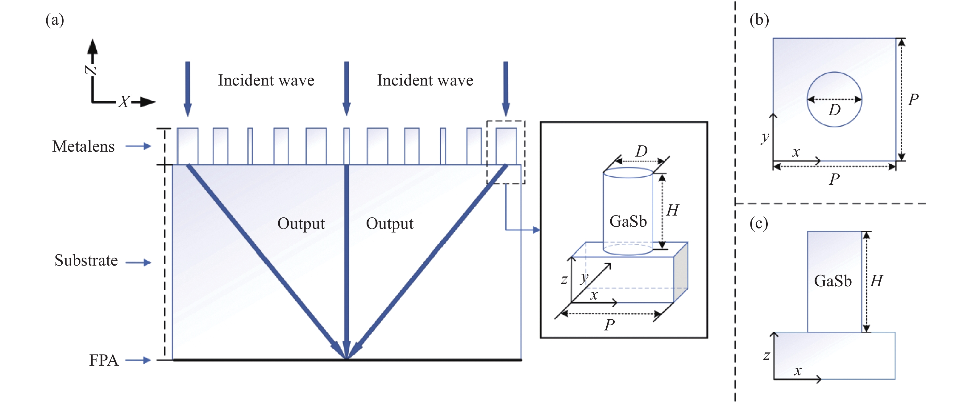
Fig. 1. Design of the metalens. (a) Working principle of the metalens and schematic diagram of the structural unit; (b), (c) Top view and side view of the structural unit, respectively, where period P , diameter D and height H of the dielectric cylinder is marked
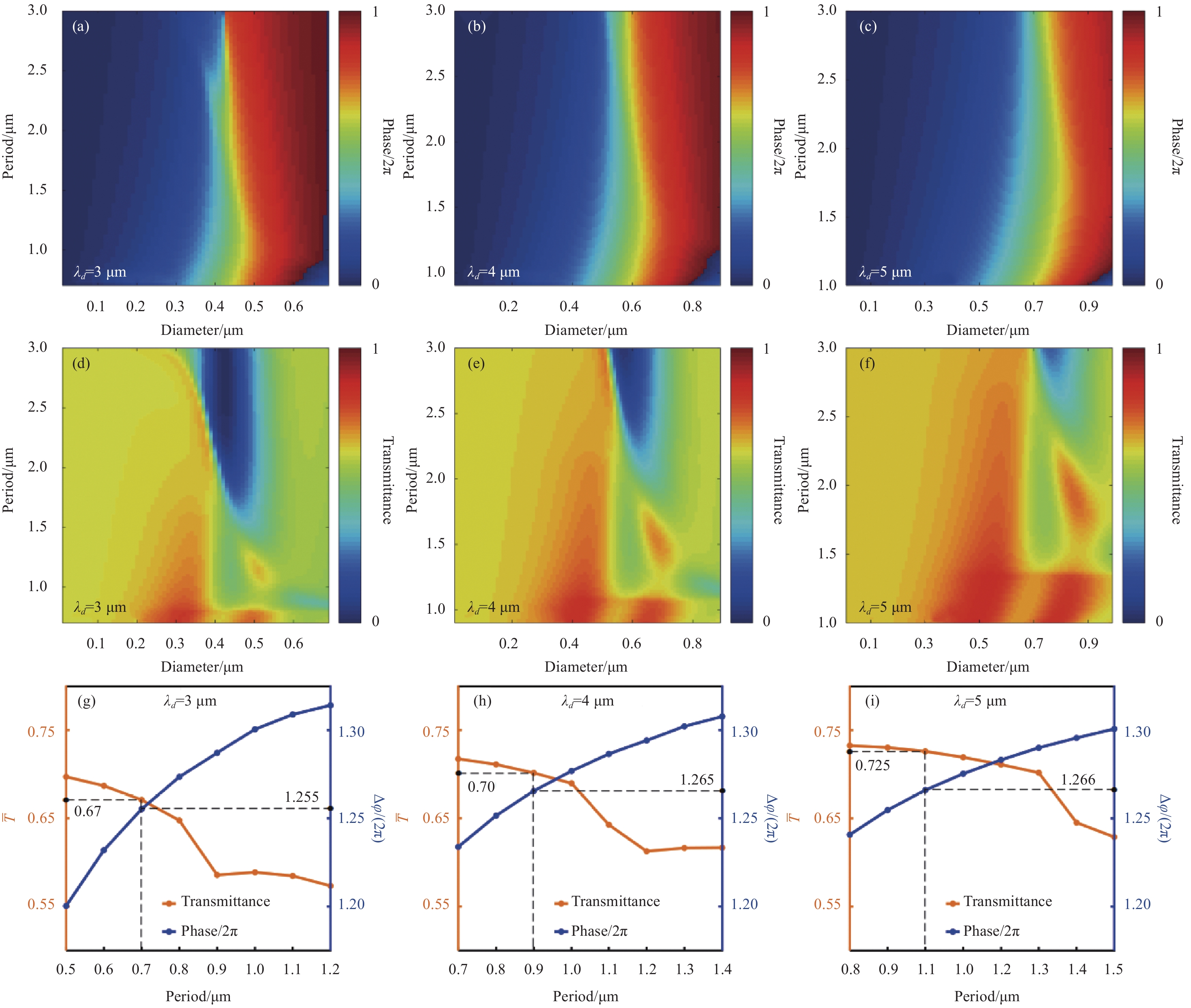
Fig. 2. Phase response of the structural unit as a function of period P and diameter D of the dielectric cylinder at the operating wavelengths of (a) 3 μm, (b) 4 μm and (c) 5 μm, respectively. Transmittance of energy flow as a function of period P and diameter D of the dielectric cylinder at the operating wavelengths of (d) 3 μm, (e) 4 μm and (f) 5 μm, respectively. Phase coverage
and average transmittance of energy flow
at (g) 3 μm, (h) 4 μm and (i) 5 μm operating wavelengths, respectively, when the diameter D changes within the allowable range under different period P of the structural unit
(a) 3 μm、(b) 4 μm和(c) 5 μm工作波长下结构单元相位随周期P 和介质柱直径D 的变化;(d) 3 μm、(e) 4 μm和(f) 5 μm工作波长下能流透过率随周期P 和介质柱直径D 的变化;(g) 3 μm、(h) 4 μm和(i) 5 μm工作波长下,取不同的周期P ,当直径D 在允许范围内变化时,对应的结构单元相位覆盖范围
和平均能流透过率
Fig. 3. Phase response of the structural unit as a function of height H and diameter D of the dielectric cylinder at the operating wavelengths of (a) 3 μm, (b) 4 μm and (c) 5 μm, respectively. Transmittance of energy flow as a function of height H and diameter D of the dielectric cylinder at the operating wavelengths of (d) 3 μm, (e) 4 μm and (f) 5 μm, respectively. Phase coverage
and average transmittance of energy flow
at (g) 3 μm, (h) 4 μm and (i) 5 μm operating wavelengths, respectively, when the diameter D changes within the allowable range under different height H of the structural unit
(a) 3 μm、(b) 4 μm和(c) 5 μm工作波长下结构单元产生的相位随介质柱高度H 和直径D 的变化;(d) 3 μm、(e) 4 μm和(f) 5 μm工作波长下能流透过率随介质柱高度H 和直径D 的变化;(g) 3 μm、(h) 4 μm和(i) 5 μm工作波长下,取不同的介质柱高度H ,当直径D 在允许范围内变化时,对应的结构单元相位覆盖范围
和平均能流透过率
Fig. 4. Transmittance of energy flow and phase response of the optimal structural unit at the operating wavelengths of (a) 3 μm, (b) 4 μm and (c) 5 μm (The size of the optimal structural unit at corresponding design wavelengths are marked in the insets)
Fig. 5. The focusing performance of the metalens in the x -z plane at operating wavelengths of 3 μm, 4 μm and 5 μm. (a) λ d = 3 μm,f = 98.4 μm, the focusing efficiency is 70.7%; (b) λ d = 4 μm,f = 97.7 μm, the focusing efficiency is 70.5%; (c) λ d = 5 μm, f = 97 μm, the focusing efficiency is 70.4%; (d)-(f) Normalized energy flow distribution along the x direction at the focal plane (white dotted line in the figure) at the operating wavelengths of 3 μm, 4 μm and 5 μm, and the full width at half-maximum (FWHM) of the focus is marked
Fig. 6. Dispersion characteristics of the metalens within ±0.5 μm of the design wavelength. The metalens with a design wavelength of 3 μm within the 2.5-3.5 μm wavelength range: (a) Normalized energy flow of the light field along the z- axis direction (x = 0), (b) the relationship between the focal position and the incident wavelength. The metalens with a design wavelength of 4 μm within the wavelength range of 3.5-4.5 μm: (c) Normalized energy flow of the light field along the z- axis direction (x = 0), (d) the relationship between the focal position and the incident wavelength. The metalens with a design wavelength of 5 μm within the 4.5-5.5 μm wavelength range: (e) Normalized energy flow of the light field along the z- axis direction (x = 0), (f) the relationship between the focal position and the incident wavelength

Set citation alerts for the article
Please enter your email address
© Copyright 2018-2021 | Chinese Laser Press. All Rights Reserved 沪ICP备15018463号-20